6F3B0253
7. Instructions
Data table:
Register
RW100
RW101
RW102
RW103
RW104
RW105
RW106
RW107
RW176
RW177
RW178
RW179
Data contents
#0 Operating frequency
#0 Output terminal status
No use
No use
#1 Operating frequency
#1 Output terminal status
No use
No use
#19 Operating frequency
#19 Output terminal status
No use
No use
Signal direction
←Read
←Read
←Read
←Read
←Read
←Read
•The data format for the operating frequency register is 0.01 Hz units. For example, if it is 60 Hz, the corresponding register data is 6000.
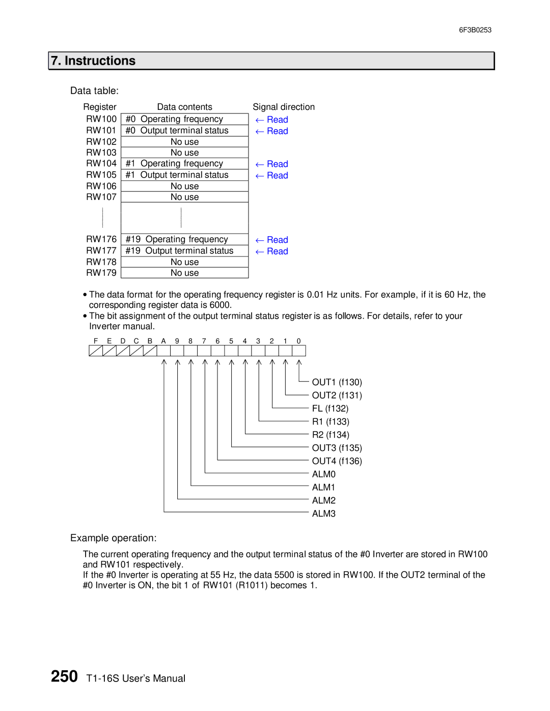
•The bit assignment of the output terminal status register is as follows. For details, refer to your Inverter manual.
F E D C B A 9 8 7 6 5 4 3 2 1 0
OUT1 (f130)
OUT2 (f131)
FL (f132)
R1 (f133)
R2 (f134)
OUT3 (f135)
OUT4 (f136)
ALM0
ALM1
ALM2
ALM3
Example operation:
The current operating frequency and the output terminal status of the #0 Inverter are stored in RW100 and RW101 respectively.
If the #0 Inverter is operating at 55 Hz, the data 5500 is stored in RW100. If the OUT2 terminal of the #0 Inverter is ON, the bit 1 of RW101 (R1011) becomes 1.