6F3B0253
7. Instructions
FUN 121
DEC
Decode
Expression
Input − [ A DEC (n) B ]− Output
Function
When the input is ON, this instruction sets the bit position which is designated by lower n bits of A to ON in the bit table, size 2n bits starting with 0 bit (LSB) of B, and resets all other bits to OFF.
Execution condition
Input |
| Operation | Output |
OFF | No execution |
| OFF |
ON | Execution |
| ON |
Operand
| Name |
|
| Device |
|
|
|
|
|
|
|
| Register |
|
|
|
| Constant | Index | ||
|
| X | Y | R | S | T. | C. | XW | YW | RW | SW | T | C | D | I | J | K |
|
| ||
A | Decode source |
|
|
|
|
|
| √ | √ | √ | √ |
| √ | √ | √ | √ | √ | √ |
|
|
|
n | Table size |
|
|
|
|
|
|
|
|
|
|
|
|
|
|
|
|
|
| 1 - 8 |
|
B | Start of table |
|
|
|
|
|
|
| √ |
| √ | √ | √ | √ | √ |
|
|
|
|
|
|
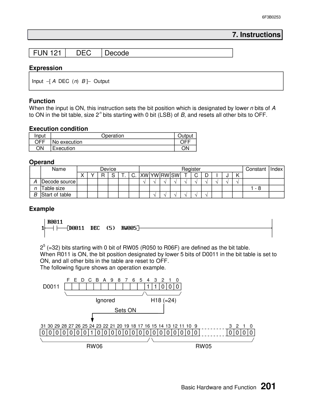
Example
25 (=32) bits starting with 0 bit of RW05 (R050 to R06F) are defined as the bit table.
When R011 is ON, the bit position designated by lower 5 bits of D0011 in the bit table is set to ON, and all other bits in the table are reset to OFF.
The following figure shows an operation example.
D0011
F E D C B A 9 8 7 6 5 4 3 2 1 0
|
|
|
|
|
|
|
|
|
|
| 1 | 1 | 0 | 0 | 0 |
Ignored | H18 (=24) |
Sets ON
31 30 29 28 27 26 25 24 23 22 21 20 19 18 17 16 15 14 13 12 11 10 9
0 | 0 | 0 | 0 | 0 | 0 | 0 | 1 | 0 |
| 0 | 0 | 0 | 0 | 0 | 0 | 0 | 0 | 0 | 0 | 0 | 0 | 0 | 0 |
|
|
|
|
|
|
| RW06 |
|
|
|
|
|
|
|
|
|
|
|
|
| RW05 | ||||
3 2 1 0
0 0 0 0
Basic Hardware and Function 201