6F3B0253
7. Instructions
FUN 185
7SEG
7 segment decode
Expression
Input − [ A 7SEG B ]− Output
Function
When the input is ON, this instruction converts the lower 4 bits data of A into the 7 segment code, and stores it in B. The 7 segment code is normally used for a numeric display LED.
Execution condition
Input |
| Operation | Output |
OFF | No execution |
| OFF |
ON | Execution |
| ON |
Operand
| Name |
|
| Device |
|
|
|
|
|
|
|
| Register |
|
|
|
|
| Constant | Index | ||
|
| X | Y | R | S | T. | C. | XW | YW | RW | SW | T | C | D | I |
| J | K |
|
| ||
A | Source |
|
|
|
|
|
| √ | √ | √ | √ |
| √ | √ | √ | √ | √ | √ |
| √ |
|
|
B | Destination |
|
|
|
|
|
|
| √ |
| √ | √ | √ | √ | √ | √ | √ |
| √ |
|
|
|
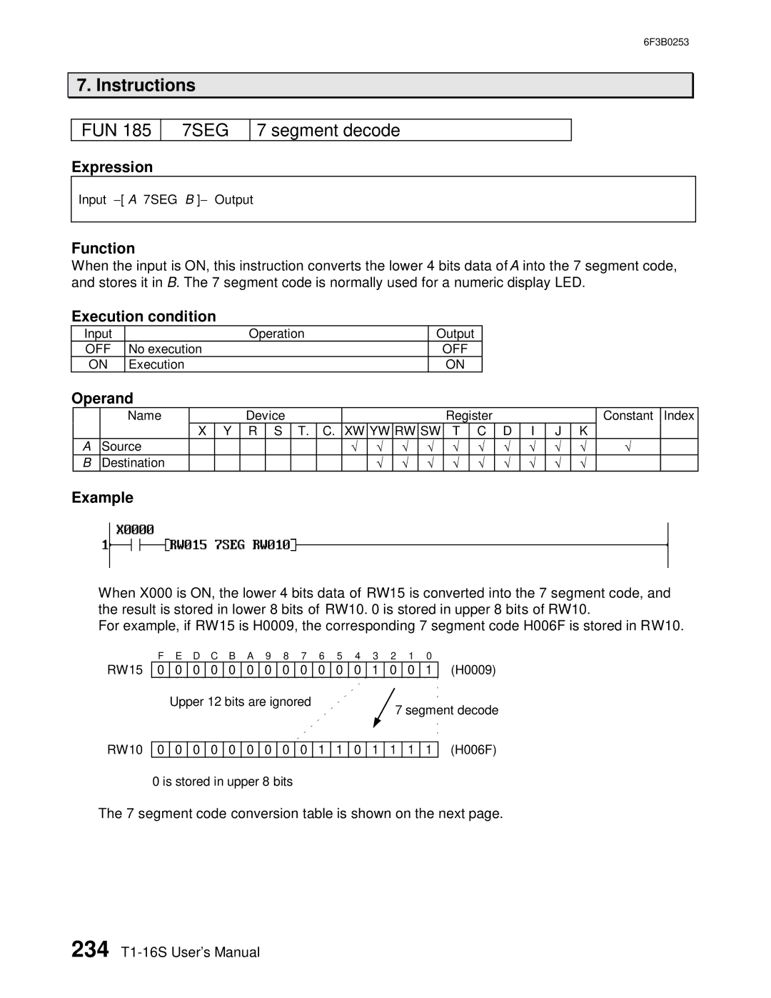
Example
When X000 is ON, the lower 4 bits data of RW15 is converted into the 7 segment code, and the result is stored in lower 8 bits of RW10. 0 is stored in upper 8 bits of RW10.
For example, if RW15 is H0009, the corresponding 7 segment code H006F is stored in RW10.
RW15
F E D C B A 9 8 7 6 5 4 3 2 1 0
0 | 0 | 0 | 0 | 0 | 0 | 0 | 0 | 0 | 0 | 0 | 0 | 1 | 0 | 0 | 1 | (H0009) | |
| Upper 12 bits are ignored |
|
|
|
|
|
|
|
|
| |||||||
|
|
|
|
|
| 7 segment decode | |||||||||||
|
|
|
|
|
|
|
|
|
|
|
|
|
| ||||
|
|
|
|
|
|
|
|
|
|
|
|
|
|
|
|
|
|
RW10
0 | 0 | 0 | 0 | 0 | 0 | 0 | 0 | 0 | 1 | 1 | 0 | 1 | 1 | 1 | 1 |
0 is stored in upper 8 bits |
|
|
|
|
|
|
|
| |||||||
(H006F)
The 7 segment code conversion table is shown on the next page.
234