6F3B0253
|
| 1. System Configuration | ||
| I/O status LEDs: |
|
|
|
| Indicates the ON/OFF status of each I/O signal. (color: red) |
|
| |
|
|
|
|
|
| SW54 setting | I/O intending for an indication | Note |
|
| value |
|
|
|
| 0 (default) | Basic unit (L: |
|
|
| 1 | I/O module slot 0 | It indicates these at the |
|
| 2 | I/O module slot 1 | time of only RUN |
|
| 3 | I/O module slot 2 | mode. |
|
| 4 | I/O module slot 3 |
|
|
| 5 | I/O module slot 4 |
|
|
| 6 | I/O module slot 5 |
|
|
| 7 | I/O module slot 6 |
|
|
| 8 | I/O module slot 7 |
|
|
| 9 |
|
| |
| 10 |
|
| |
| Others | Basic unit (L: |
|
|
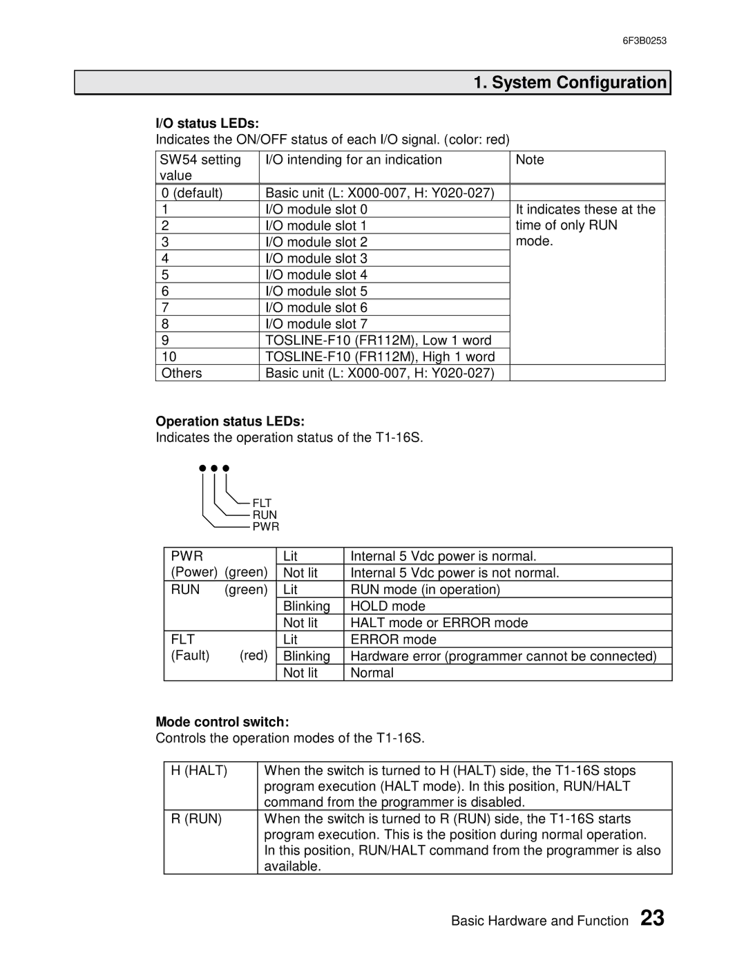
Operation status LEDs:
Indicates the operation status of the
FLT
RUN
PWR
PWR |
| Lit | Internal 5 | Vdc power is normal. |
(Power) (green) | Not lit | Internal 5 | Vdc power is not normal. | |
RUN | (green) | Lit | RUN mode (in operation) | |
|
| Blinking | HOLD mode | |
|
| Not lit | HALT mode or ERROR mode | |
FLT |
| Lit | ERROR mode | |
(Fault) | (red) | Blinking | Hardware error (programmer cannot be connected) | |
|
| Not lit | Normal |
|
Mode control switch:
Controls the operation modes of the
H (HALT) | When the switch is turned to H (HALT) side, the |
| program execution (HALT mode). In this position, RUN/HALT |
| command from the programmer is disabled. |
R (RUN) | When the switch is turned to R (RUN) side, the |
| program execution. This is the position during normal operation. |
| In this position, RUN/HALT command from the programmer is also |
| available. |
| Basic Hardware and Function 23 |