6F3B0253
7.Instructions
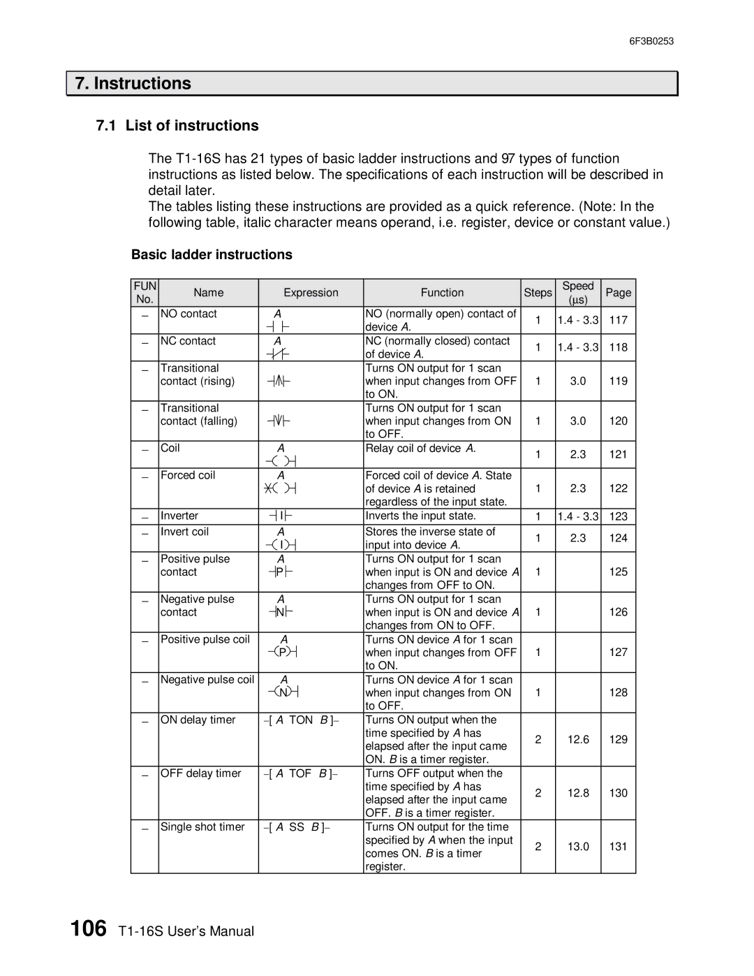
7.1List of instructions
The
The tables listing these instructions are provided as a quick reference. (Note: In the following table, italic character means operand, i.e. register, device or constant value.)
Basic ladder instructions
FUN | Name |
|
|
|
| Expression | Function | Steps | Speed | Page | ||||||
No. |
|
|
|
|
|
|
|
|
|
|
|
|
|
| (∝ s) |
|
− | NO contact |
|
|
| A |
| NO (normally open) contact of | 1 | 1.4 - 3.3 | 117 | ||||||
|
|
|
|
|
|
|
|
|
|
|
|
| device A. | |||
|
|
|
|
|
|
|
|
|
|
|
|
|
|
|
| |
− | NC contact |
|
|
| A |
| NC (normally closed) contact | 1 | 1.4 - 3.3 | 118 | ||||||
|
|
|
|
|
|
|
|
|
|
|
|
| of device A. | |||
|
|
|
|
|
|
|
|
|
|
|
|
|
|
|
| |
− | Transitional |
|
|
|
|
|
|
|
|
|
|
| Turns ON output for 1 scan |
|
|
|
| contact (rising) |
|
|
|
|
|
|
|
|
|
|
| when input changes from OFF | 1 | 3.0 | 119 |
|
|
|
|
|
|
|
|
|
|
|
|
| to ON. |
|
|
|
− | Transitional |
|
|
|
|
|
|
|
|
|
|
| Turns ON output for 1 scan |
|
|
|
| contact (falling) |
|
|
|
|
|
|
|
|
|
|
| when input changes from ON | 1 | 3.0 | 120 |
|
|
|
|
|
|
|
|
|
|
|
|
| to OFF. |
|
|
|
− | Coil |
|
|
|
| A |
| Relay coil of device A. | 1 | 2.3 | 121 | |||||
|
|
|
|
|
|
|
|
|
|
|
|
|
| |||
|
|
|
|
|
|
|
|
|
|
|
|
|
|
|
| |
− | Forced coil |
|
|
|
| A |
| Forced coil of device A. State |
|
|
| |||||
|
|
|
|
|
|
|
|
|
|
|
|
| of device A is retained | 1 | 2.3 | 122 |
|
|
|
|
|
|
|
|
|
|
|
|
| regardless of the input state. |
|
|
|
− | Inverter |
|
|
|
| I |
|
|
|
| Inverts the input state. | 1 | 1.4 - 3.3 | 123 | ||
|
|
|
|
|
|
| ||||||||||
|
|
|
|
|
| |||||||||||
− | Invert coil |
|
|
|
| A |
| Stores the inverse state of | 1 | 2.3 | 124 | |||||
|
|
|
|
|
| I |
| input into device A. | ||||||||
|
|
|
|
|
|
|
|
|
| |||||||
− | Positive pulse |
|
|
|
| A |
| Turns ON output for 1 scan | 1 |
| 125 | |||||
| contact |
|
|
|
| P |
| when input is ON and device A |
| |||||||
|
|
|
|
|
|
|
|
|
|
|
|
| changes from OFF to ON. |
|
|
|
− | Negative pulse |
|
|
|
| A |
| Turns ON output for 1 scan | 1 |
| 126 | |||||
| contact |
|
|
|
| N |
| when input is ON and device A |
| |||||||
|
|
|
|
|
|
|
|
|
|
|
|
| changes from ON to OFF. |
|
|
|
− | Positive pulse coil |
|
|
|
| A |
| Turns ON device A for 1 scan | 1 |
| 127 | |||||
|
|
|
|
|
| P |
| when input changes from OFF |
| |||||||
|
|
|
|
|
|
|
|
|
|
|
|
| to ON. |
|
|
|
− | Negative pulse coil |
|
|
|
| A |
| Turns ON device A for 1 scan | 1 |
| 128 | |||||
|
|
|
|
|
| N |
| when input changes from ON |
| |||||||
|
|
|
|
|
|
|
|
|
|
|
|
| to OFF. |
|
|
|
− | ON delay timer | − [ A TON | B ]− | Turns ON output when the |
|
|
| |||||||||
|
|
|
|
|
|
|
|
|
|
|
|
| time specified by A has | 2 | 12.6 | 129 |
|
|
|
|
|
|
|
|
|
|
|
|
| elapsed after the input came | |||
|
|
|
|
|
|
|
|
|
|
|
|
|
|
|
| |
|
|
|
|
|
|
|
|
|
|
|
|
| ON. B is a timer register. |
|
|
|
− | OFF delay timer | − [ A TOF | B ]− | Turns OFF output when the |
|
|
| |||||||||
|
|
|
|
|
|
|
|
|
|
|
|
| time specified by A has | 2 | 12.8 | 130 |
|
|
|
|
|
|
|
|
|
|
|
|
| elapsed after the input came | |||
|
|
|
|
|
|
|
|
|
|
|
|
|
|
|
| |
|
|
|
|
|
|
|
|
|
|
|
|
| OFF. B is a timer register. |
|
|
|
− | Single shot timer | − [ A SS B ]− | Turns ON output for the time |
|
|
| ||||||||||
|
|
|
|
|
|
|
|
|
|
|
|
| specified by A when the input | 2 | 13.0 | 131 |
|
|
|
|
|
|
|
|
|
|
|
|
| comes ON. B is a timer | |||
|
|
|
|
|
|
|
|
|
|
|
|
|
|
|
| |
|
|
|
|
|
|
|
|
|
|
|
|
| register. |
|
|
|
106