6F3B0253
3.I/O Application Precautions
3.2Application precautions for output signals
! | WARNING | Configure emergency stop and safety interlocking circuits outside the |
|
| |
|
| accidents |
! | CAUTION | 1. Turn on power to the |
Failure to do so may cause unexpected behavior of the loads.
2. Configure the external circuit so that the external 24Vdc power required for the transistor output circuits and power to the loads are switched on/off simultaneously. Also, turn off power to the loads before turning off power to the
3. Install fuses appropriate to the load current in the external circuits for the outputs. Failure to do so can cause fire in case of load
(1) 2 points of
The leading 2 points of output (Y020 and Y021) are
These
Note that the specifications of the
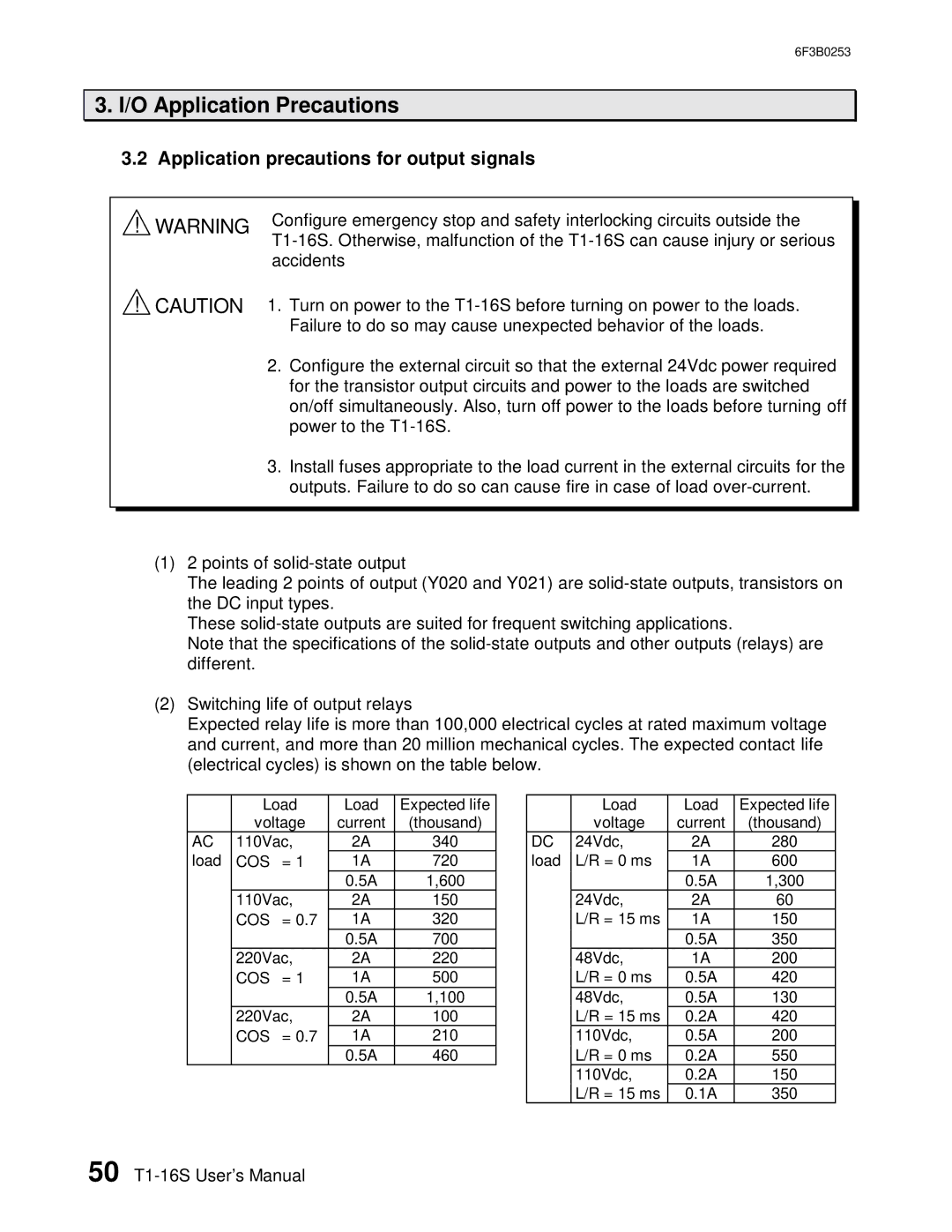
(2) Switching life of output relays
Expected relay life is more than 100,000 electrical cycles at rated maximum voltage and current, and more than 20 million mechanical cycles. The expected contact life (electrical cycles) is shown on the table below.
| Load | Load | Expected life |
| voltage | current | (thousand) |
AC | 110Vac, | 2A | 340 |
load | COSφ = 1 | 1A | 720 |
|
| 0.5A | 1,600 |
| 110Vac, | 2A | 150 |
| COSφ = 0.7 | 1A | 320 |
|
| 0.5A | 700 |
| 220Vac, | 2A | 220 |
| COSφ = 1 | 1A | 500 |
|
| 0.5A | 1,100 |
| 220Vac, | 2A | 100 |
| COSφ = 0.7 | 1A | 210 |
|
| 0.5A | 460 |
| Load | Load | Expected life |
| voltage | current | (thousand) |
DC | 24Vdc, | 2A | 280 |
load | L/R = 0 ms | 1A | 600 |
|
| 0.5A | 1,300 |
| 24Vdc, | 2A | 60 |
| L/R = 15 ms | 1A | 150 |
|
| 0.5A | 350 |
| 48Vdc, | 1A | 200 |
| L/R = 0 ms | 0.5A | 420 |
| 48Vdc, | 0.5A | 130 |
| L/R = 15 ms | 0.2A | 420 |
| 110Vdc, | 0.5A | 200 |
| L/R = 0 ms | 0.2A | 550 |
| 110Vdc, | 0.2A | 150 |
| L/R = 15 ms | 0.1A | 350 |
50