6F3B0253
7. Instructions
FUN 147
F/F
Flip-flop
Expression
Set input | − |
Reset input −
SF/F Q − Output
RA
Function
When the set input is ON, the device A is set to ON. When the reset input is ON, the device A is reset to OFF. When both the set and reset inputs are OFF, the device A remains the state. If both the set and reset inputs are ON, the device A is reset to OFF.
The state of the output is the same as the device A.
Execution condition
Set | Reset | Operation | Output |
input | input |
|
|
OFF | OFF | No execution (A remains previous state) | Same |
| ON | Resets A to OFF | as A |
ON | OFF | Sets A to ON |
|
| ON | Resets A to OFF |
|
Operand
| Name |
|
| Device |
|
|
|
|
|
| Register |
|
| Constant | Index | ||||
|
| X | Y | R | S | T. | C. | XW | YW | RW | SW | T | C | D | I | J | K |
|
|
A | Device |
| √ | √ | √ |
|
|
|
|
|
|
|
|
|
|
|
|
|
|
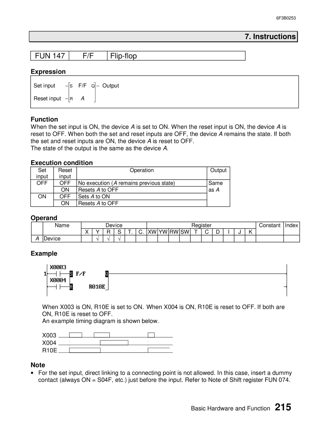
Example
When X003 is ON, R10E is set to ON. When X004 is ON, R10E is reset to OFF. If both are ON, R10E is reset to OFF.
An example timing diagram is shown below.
X003
X004
R10E
Note
•For the set input, direct linking to a connecting point is not allowed. In this case, insert a dummy contact (always ON = S04F, etc.) just before the input. Refer to Note of Shift register FUN 074.
Basic Hardware and Function 215