SX6T/SX8T Series
Table of Contents
Test Print
Printer Parameter Fine Adjustment
Rfid Analyze Tool
On Line Mode
Program Down Load
Key Operation Flow
Introduction
Operation Panel
→ Section
This is the start of the IP Address Setting menu. → Section
10RFID Pause
This is the start of the Basic Setting menu
This is the Rfid Module Setting menu
8BASIC Pause
PRT Type Transfr
Self-diagnostic Test
„ Outline of Self-diagnostic Test
„ How to Enter Self-diagnostic Test Mode
PRT Type Direct
Printing Mode Selection
Dispensing Mode Selection
PRT Type no Tran
Maintenance Checking & Print
Maintenance Counter/Parameter Settings Print Out
Stabilizer Auto Calib OFF LAN On Snmp on Prtr IP Address
Descriptions of the Maintenance Counter
Font
Descriptions of the Parameters
¶¶-¶¶-¶¶-¶¶-¶¶-¶¶
Basic
After printing is completed, the display returns to 1DIAG
Self-Diagnostic Test and Result Print Out
Print Sample
Eeprom Check
Descriptions
Alphanumeric Font ROM Check
Kanji ROM Check
Sdram Capacity
Sensor/Switch Print status description
Sensor/Thermistor
Sensor 2 Check
=300 GNDhms
Manual Threshold Check
DIN
Internal Serial Interface Check
Rfid module check Results of a Rfid module check is printed
Press the Pause key to return to 1DIAG
Print Head Element Check
Outline of Parameter Setting
Parameter Setting
After selecting a character code, press the Pause key
How to Enter Parameter Setting Mode
Character Code Selection
Use the Feed or Restart key to select a desired option
After selecting a baud rate, press the Pause key
Character Zero Selection
Baud Rate Selection
After selecting a character zero, press the Pause key
After selecting a stop bit, press the Pause key
Data Length Selection
Stop Bit Length Selection
After selecting a data length, press the Pause key
After selecting the parity, press the Pause key
Parity Selection
Flow Control Code Selection
After selecting a language, press the Pause key
LCD Language Selection
Auto Forward Wait Selection
Ribbon Save Function Selection
Head Up Cut Selection
2PARAMETER SET Control CODE1 1B
Control Code Selection
2PARAMETER SET Code Auto
Code Auto Code ESC,LF,NUL Code Manual
After selecting the Strip Wait Status, press the Pause key
Ribbon Type Selection
Strip Wait Status Selection
After selecting a ribbon type, press the Pause key
Euro Code Selection
Feed Key Function Selection
Kanji Code Selection
After selecting an ACK/BUSY timing, press the Pause key
Auto Print Head Check Selection
Centronics Interface ACK/BUSY Timing Selection
After selecting auto print head check, press the Pause key
After selecting the media sensor type, press the Pause key
Web Printer Function Selection
Media Sensor Selection
After selecting the Input Prime, press the Pause key
Input Prime Selection
Expansion I/O Interface Type Selection
After selecting a Plug & Play, press the Pause key
Plug & Play Selection
Label End/Ribbon End Selection
TYPE1
Press the Pause key to skip
Maxi Code Specification Selection
Pre-Strip Selection
Reverse Feed Speed Selection
2PARAMETER SET Stabilizer on
Strip Motor Torque Selection
Stabilizer Function Selection
2PARAMETER SET Peel OFF TRQ R0
Outline of Printer Parameter Fine Adjustment
Printer Parameter Fine Adjustment
3ADJUST SET
How to Enter Printer Parameter Fine Adjustment Mode
Print Start Position Fine Adjustment Example
Print Start Position Fine Adjustment
After completing the fine adjustment, press the Pause key
When setting +0.0 mm
2 Cut/Strip Position Fine Adjustment
Example of Cut Position Fine Adjustment
Prevention by fine adjustment of the cut position
Example of Strip Position Fine Adjustment
Operation example Issue count 3, Cut interval
Example of Reverse Feed Amount Fine Adjustment
Reverse Feed Amount Fine Adjustment
Coordinate Fine Adjustment
Example of X Coordinate Fine Adjustment
Darker Standard Lighter
Maximum fine adjustment value
High Standard Low
Ribbon Motor Voltage Fine Adjustment Feed/Take-up Motor
3ADJUST SET THRESHOLDT1.4V
Threshold Manual Fine Adjustment Black Mark/Feed Gap Sensor
3ADJUST SET THRESHOLDR1.0V
Outline of Test Print
Test Print
4TEST Print
How to Enter Test Print Mode
Media Ribbon Save Area 8 mm
Specifying the Print Condition for the Test Print
Issue Count Setting
Select an issue count from a range of 1 to
Print Speed Setting
Sensor Type Selection
Printing Mode Selection
Issue Mode Selection
4TEST Print Paper Feed
Media Length Setting
Paper Feed Selection
Test Print Pattern Selection
Slant Line 1 dot
Print Sample of Slant Line 3 dots
Slant Line 3 dots
Print Sample of Barcodes
Characters
Barcode
Print Sample of Characters
Print Sample of Factory Test
Non-Printing
Factory Test
Print Sample of Non-print
Prints characters on 5 pieces of media
Auto Print
Pause key
Prints bar codes on 5 pieces of media
Outline of the Sensor Adjustment
Sensor Adjustment
5SENSOR ADJ
Black Mark Sensor Adjustment
How to Enter the Sensor Adjustment Mode
Thermistor Status Display
5SENSOR ADJ. Trans
Feed Gap Sensor Adjustment
Ribbon End Sensor Adjustment Ribbon Level
Press the Pause key to return to 5SENSOR ADJ. display
6RAM Clear
How to Enter RAM Clear Mode
RAM Clear
Outline of RAM Clear
SX6T-TS12-QM-R and B-SX8T-TS12-QM-R V1.0B or earlier
Maintenance Counter Clear
RAM Clear Menu Selection
No RAM Clear
Mode
Parameter Clear
Solenoid drive time for head up
Initial values after clearing the parameters Parameter Clear
170.6 mm
7IP Address
IP Address Setting
Outline of the IP Address Setting
How to Enter IP Address Setting Mode
Printer IP Adres
When Printer IP Adres is displayed, press the Pause key
Set the IP address using the following procedure
To enter each sub menu, press the Pause key
To set a socket port number, follow the procedure below
Socket Port Setting
Dhcp and Dhcp Client ID Setting
Ascii code and Hex. code correspondence table
Dhcp Host Name Setting
Mode Ascii Dhcp Host Name
Mode Ascii
8BASIC
Basic Setting
How to Enter Basic Setting Mode
Outline of Basic Setting
Basic File Browser
Basic Specification Selection Mode
Basic Trace Selection Mode
Basic Expansion Mode Execution of Basic Program
Outline of the Rfid Module Setting
Rfid Module Setting
Press the Restart key or Feed key until 10RFID appears
How to Enter Rfid Module Setting Mode
Read Test Procedure
Rfid Read Test
Module None Module U2
Rfid Module Type Selection
Module None
Rfid Tag Type Selection
Rfid Error Tag Detection
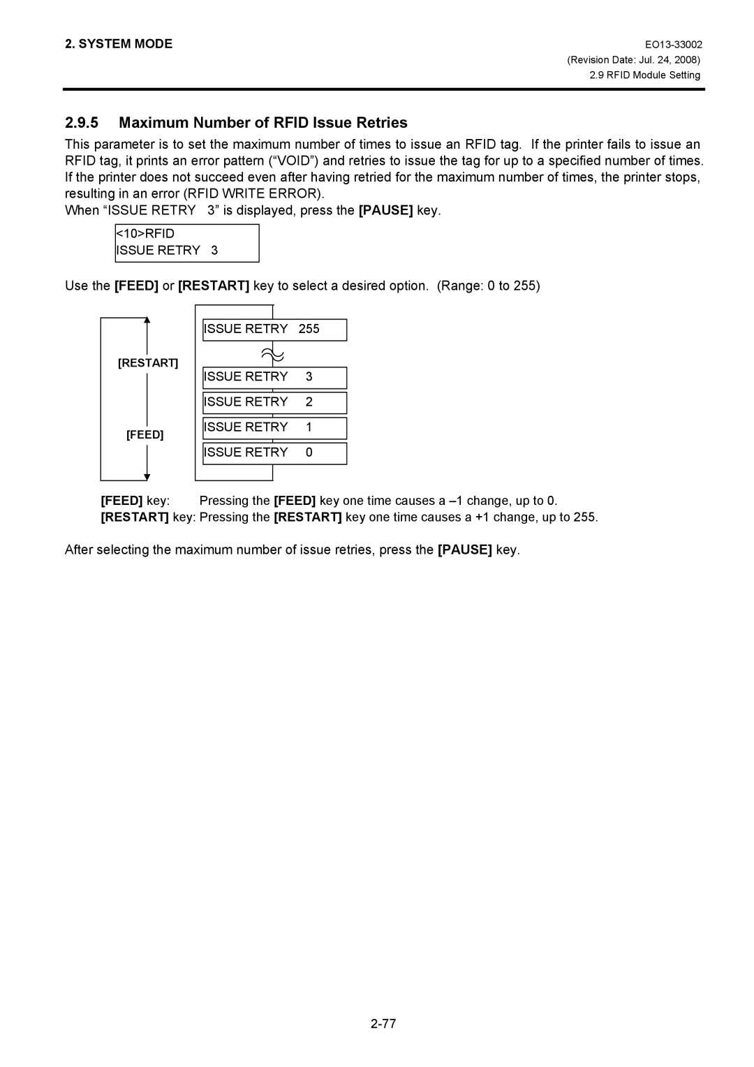
Issue Retry
Maximum Number of Rfid Issue Retries
Cycle CNT
Maximum Number of Rfid Read Retries
Cycle TIM
Rfid Read Retry Time-out
After selecting the time-out, press the Pause key
Maximum Number of Rfid Write Retries
Rfid Write Retry Time-out
After selecting the adjustment value, press the Pause key
Rfid Adjustment for Retry
Adjustment in negative − direction
Adjustment in positive + direction
Rfid AGC Threshold
Rfid Wireless Power Level Setting
When AGC Threshold is displayed, press the Pause key
Power Level
Qvalue
Rfid Module Q Value Setting
Value
WT AGC
AGC Threshold for Data Write Setting
When WT AGC is displayed, press the Pause key
WT MIN AGC
AGC Threshold Lower Limit for Retry Setting
On Line Mode
„ LCD message and LED indication
Symbols in the message
Rfid Write Error
System Error
„ How to Perform an Automatic Threshold Setting
Automatic Threshold Setting
„ Outline of Automatic Threshold Setting
1RESET
Reset Operation
„ How to Perform a Reset Operation
„ How to Perform a Dump Operation
Dump Mode
Required label length
Data in the receive buffer is printed as follows
Print Conditions
Receive buffer size
5EXPAND Mode
Basic Expansion Mode
„ How to Perform Basic Expansion
6AUTO Calib OFF
Automatic Calibration Setting
„ How to Choose an Automatic Calibration Setting
6AUTO Calib
On Line Mode
On Snmp on
LAN Enable/Disable Setting
„ How to Enable/Disable the LAN
8RTC SET Date M
Real Time Clock RTC Setting
„ How to perform the Real Time Clock Setting
8RTC SET
8RTC SET LOW BATT. Check
8RTC SET Time H
8RTC SET Time M
8RTC SET Time S
On Line Mode
System Requirements
Outline of Features
Download Program Installation
Before starting the download procedure
Setup
Setup Disk
Installation Procedure
First, start the printer in download mode
EO13-33002
Program Down Load
Program Down Load
Program Down Load
System Requirement
Rfid Analyze Tool
V1.5
Set up
Setup Disk Installation Setup Disk consists of one CD-ROM
SX/SA Rfid Analyze Tool
SX708-RFID-U2-EU/CN-R
Application Functions
Main Menu
U2 B-SX704-RFID-U2-EU/AU/US/CN-R
File Menu
EO13-33002
End Exit Exits from the Analyze Tool program
Tool Menu
NON, XON, XON/XOFF
PWR Level Change AGC Read Value
Sheet Setting Makes settings for the media to be used
Select the printer model
Select the test mode This menu is not available
Displays Printer Version and Rfid Module Version
Help Menu
Example
Operating Procedure
Click on the Tool menu, and choose CommSetting
RTS/CTS+XON/XOFF
SX704-RFID-U2-EU/AU/US/CN-R U2
U2 B-SA704-RFID-U2-EU/AU/US/CN-R B-SX708-RFID-U2-EU/CN-R
Tag Data
EO13-33002 Revision Date Jul Operatin Procedure
Write/Read Results Box When U2 is selected
Write/Read Results Box