Time Stamp Accuracy
Accuracy Resulting from the Combined Errors
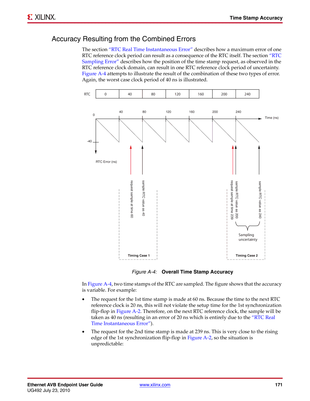
The section “RTC Real Time Instantaneous Error” describes how a maximum error of one RTC reference clock period can result as a consequence of the RTC itself. The section “RTC Sampling Error” describes how the position of the time stamp request, as observed in the RTC reference clock domain, can result in one RTC reference clock period of uncertainty. Figure
RTC
0
40
80
120
160
200
240
40 | 80 | 120 | 160 | 200 | 240 |
0 |
|
|
|
| Time (ns) |
|
|
|
|
| |
|
|
|
|
| |
RTC Error (ns) |
|
|
|
|
|
reque st | sample | reque st | sample | sample |
sample attime 60 | RTCva lue as40 | sample attime 239 | RTCva lue as200 | RTCva lue as240 |
Sampling uncertainty
Timing Case 1 | Timing Case 2 |
Figure A-4: Overall Time Stamp Accuracy
In Figure A-4, two time stamps of the RTC are sampled. The figure shows that the accuracy is variable. For example:
•The request for the 1st time stamp is made at 60 ns. Because the time to the next RTC reference clock is 20 ns, this will not violate the setup time for the 1st synchronization flip-flop in Figure A-2. Therefore, on the next RTC reference clock, the sample will be taken as 40 ns (resulting in an error of 20 ns which is entirely due to the “RTC Real Time Instantaneous Error”).
•The request for the 2nd time stamp is made at 239 ns. This is very close to the rising edge of the 1st synchronization flip-flop in Figure A-2, so the situation is unpredictable:
Ethernet AVB Endpoint User Guide | www.xilinx.com | 171 |
UG492 July 23, 2010