PLB Address Map and Register Definitions
This register and the registers defined in Table
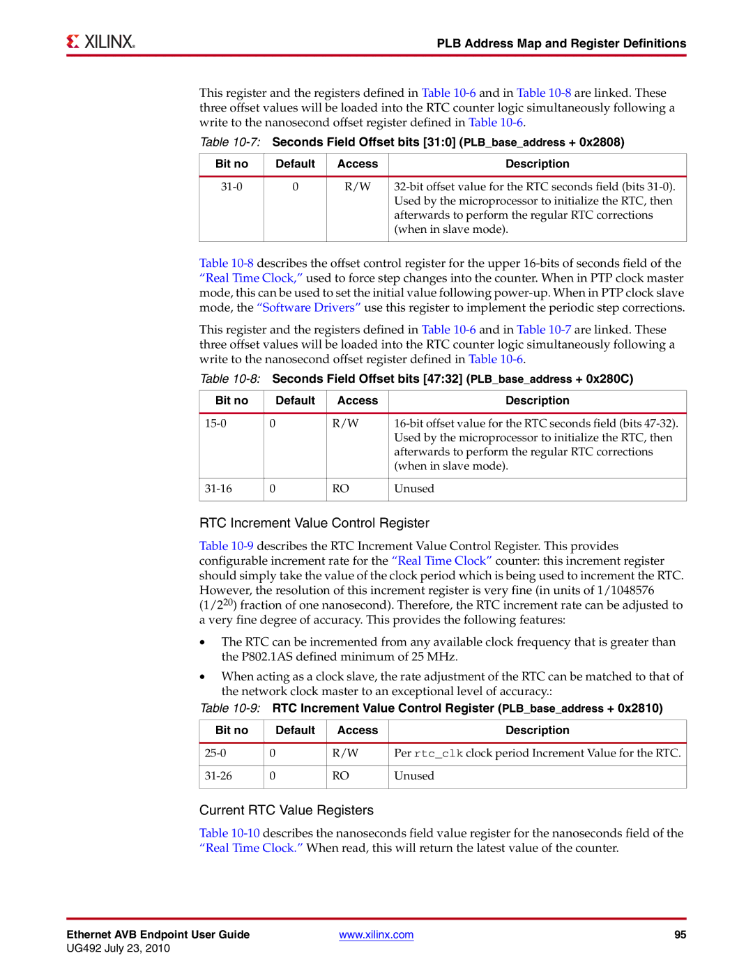
Table
Bit no | Default | Access | Description |
|
|
|
|
0 | R/W | ||
|
|
| Used by the microprocessor to initialize the RTC, then |
|
|
| afterwards to perform the regular RTC corrections |
|
|
| (when in slave mode). |
|
|
|
|
Table
This register and the registers defined in Table
Table
Bit no |
| Default | Access | Description |
|
|
|
|
|
0 |
| R/W | ||
|
|
|
| Used by the microprocessor to initialize the RTC, then |
|
|
|
| afterwards to perform the regular RTC corrections |
|
|
|
| (when in slave mode). |
|
|
|
|
|
0 |
| RO | Unused | |
|
|
|
|
|
RTC Increment Value Control Register
Table
•The RTC can be incremented from any available clock frequency that is greater than the P802.1AS defined minimum of 25 MHz.
•When acting as a clock slave, the rate adjustment of the RTC can be matched to that of the network clock master to an exceptional level of accuracy.:
Table
Bit no |
| Default | Access | Description |
|
|
|
|
|
0 |
| R/W | Per rtc_clk clock period Increment Value for the RTC. | |
|
|
|
|
|
0 |
| RO | Unused | |
|
|
|
|
|
Current RTC Value Registers
Table
Ethernet AVB Endpoint User Guide | www.xilinx.com | 95 |
UG492 July 23, 2010