Time Stamp Accuracy
RTC Sampling Error
It has to be assumed that the RTC reference clock is of a different frequency to the MAC transmitted and receiver clocks. Therefore, the RTC sampling logic has to be asynchronous.
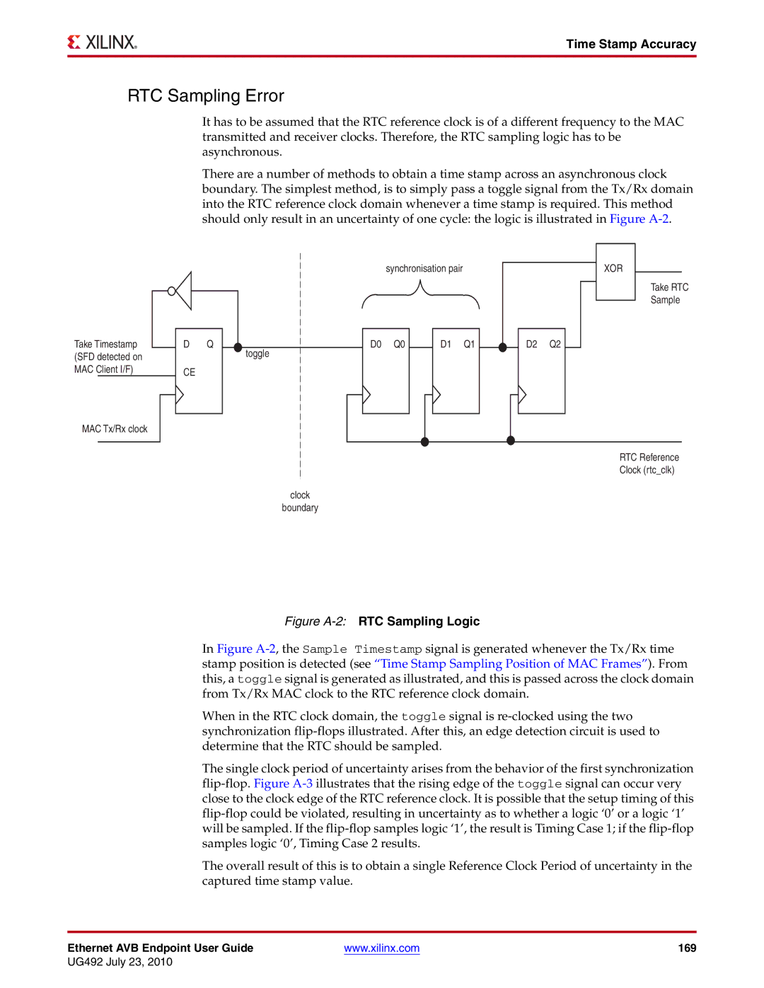
There are a number of methods to obtain a time stamp across an asynchronous clock boundary. The simplest method, is to simply pass a toggle signal from the Tx/Rx domain into the RTC reference clock domain whenever a time stamp is required. This method should only result in an uncertainty of one cycle: the logic is illustrated in Figure
Take Timestamp (SFD detected on MAC Client I/F)
MAC Tx/Rx clock
synchronisation pair
D Q |
| D0 Q0 | D1 Q1 |
toggle
CE
D2 Q2
XOR
Take RTC
Sample
RTC Reference
Clock (rtc_clk)
clock
boundary
Figure A-2: RTC Sampling Logic
In Figure A-2, the Sample Timestamp signal is generated whenever the Tx/Rx time stamp position is detected (see “Time Stamp Sampling Position of MAC Frames”). From this, a toggle signal is generated as illustrated, and this is passed across the clock domain from Tx/Rx MAC clock to the RTC reference clock domain.
When in the RTC clock domain, the toggle signal is re-clocked using the two synchronization flip-flops illustrated. After this, an edge detection circuit is used to determine that the RTC should be sampled.
The single clock period of uncertainty arises from the behavior of the first synchronization flip-flop. Figure A-3 illustrates that the rising edge of the toggle signal can occur very close to the clock edge of the RTC reference clock. It is possible that the setup timing of this flip-flop could be violated, resulting in uncertainty as to whether a logic ‘0’ or a logic ‘1’ will be sampled. If the flip-flop samples logic ‘1’, the result is Timing Case 1; if the flip-flop samples logic ‘0’, Timing Case 2 results.
The overall result of this is to obtain a single Reference Clock Period of uncertainty in the captured time stamp value.
Ethernet AVB Endpoint User Guide | www.xilinx.com | 169 |
UG492 July 23, 2010
