Rx PTP Packet Buffer
Rx PTP Packet Buffer
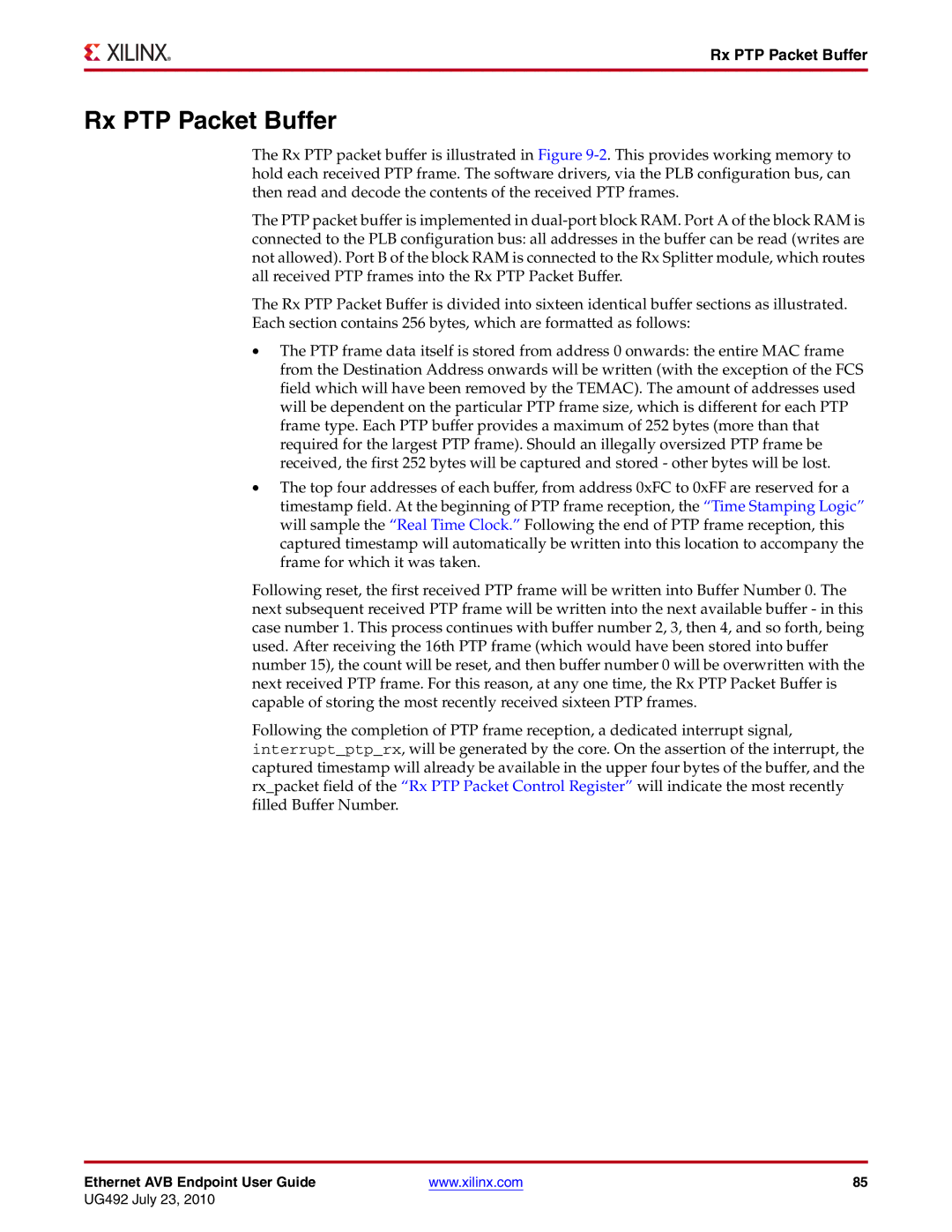
The Rx PTP packet buffer is illustrated in Figure
The PTP packet buffer is implemented in
The Rx PTP Packet Buffer is divided into sixteen identical buffer sections as illustrated. Each section contains 256 bytes, which are formatted as follows:
•The PTP frame data itself is stored from address 0 onwards: the entire MAC frame from the Destination Address onwards will be written (with the exception of the FCS field which will have been removed by the TEMAC). The amount of addresses used will be dependent on the particular PTP frame size, which is different for each PTP frame type. Each PTP buffer provides a maximum of 252 bytes (more than that required for the largest PTP frame). Should an illegally oversized PTP frame be received, the first 252 bytes will be captured and stored - other bytes will be lost.
•The top four addresses of each buffer, from address 0xFC to 0xFF are reserved for a timestamp field. At the beginning of PTP frame reception, the “Time Stamping Logic” will sample the “Real Time Clock.” Following the end of PTP frame reception, this captured timestamp will automatically be written into this location to accompany the frame for which it was taken.
Following reset, the first received PTP frame will be written into Buffer Number 0. The next subsequent received PTP frame will be written into the next available buffer - in this case number 1. This process continues with buffer number 2, 3, then 4, and so forth, being used. After receiving the 16th PTP frame (which would have been stored into buffer number 15), the count will be reset, and then buffer number 0 will be overwritten with the next received PTP frame. For this reason, at any one time, the Rx PTP Packet Buffer is capable of storing the most recently received sixteen PTP frames.
Following the completion of PTP frame reception, a dedicated interrupt signal, interrupt_ptp_rx, will be generated by the core. On the assertion of the interrupt, the captured timestamp will already be available in the upper four bytes of the buffer, and the rx_packet field of the “Rx PTP Packet Control Register” will indicate the most recently filled Buffer Number.
Ethernet AVB Endpoint User Guide | www.xilinx.com | 85 |
UG492 July 23, 2010