Chapter 2. Installation
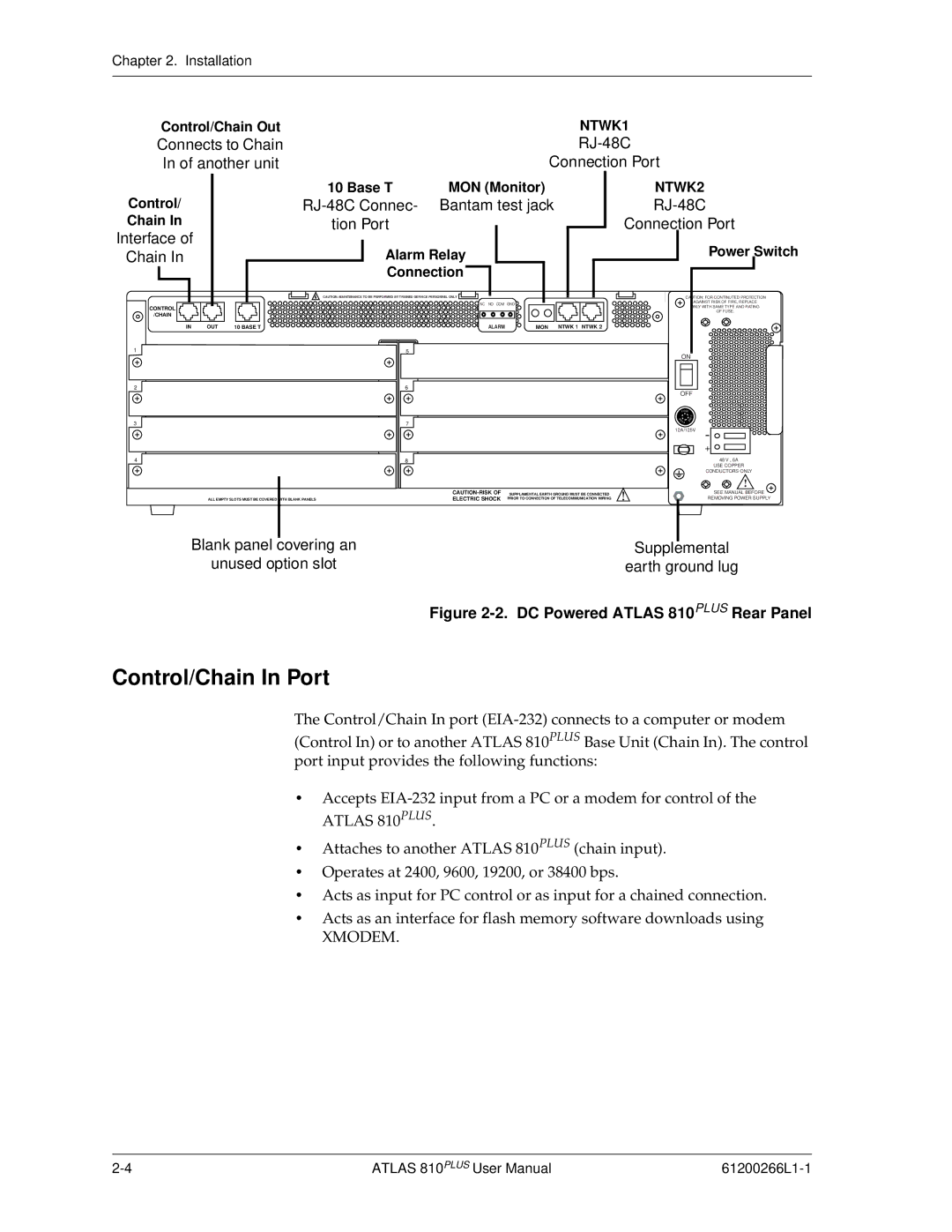
Control/Chain Out | NTWK1 |
Connects to Chain | |
In of another unit | Connection Port |
Control/
Chain In
Interface of
Chain In
CONTROL
/CHAIN
IN OUT
1
2
10 Base T | MON (Monitor) | |
| Bantam test jack | |
tion Port |
|
|
Alarm Relay |
| |
Connection |
| |
CAUTION: MAINTENANCE TO BE PERFORMED BY TRAINED SERVICE PERSONNEL ONLY |
| |
| NC NO COM GND |
|
10 BASE T | ALARM | MON NTWK 1 NTWK 2 |
5 |
|
|
6 |
|
|
NTWK2
RJ-48C
Connection Port
Power Switch
CAUTION: FOR CONTINUTED PROTECTION
AGAINST RISK OF FIRE, REPLACE
ONLY WITH SAME TYPE AND RATING
OF FUSE.
ON
OFF
3 |
|
| 7 |
| |
|
|
|
|
|
|
4 |
|
| 8 |
| |
|
|
|
|
| |
|
|
|
|
| |
| ALL EMPTY SLOTS MUST BE COVERED | WITH BLANK PANELS |
|
| ELECTRIC SHOCK PRIOR TO CONNECTION OF TELECOMMUNICATION WIRING |
Blank panel covering an
unused option slot
FUSE |
|
| F |
E | U |
S | E S |
UF |
|
12A/125V -
+ ![]()
![]()
48 V , 6A
USE COPPER
CONDUCTORS ONLY
!
SEE MANUAL BEFORE
REMOVING POWER SUPPLY
Supplemental
earth ground lug
Figure 2-2. DC Powered ATLAS 810PLUS Rear Panel
Control/Chain In Port
The Control/Chain In port
•Accepts
•Attaches to another ATLAS 810PLUS (chain input).
•Operates at 2400, 9600, 19200, or 38400 bps.
•Acts as input for PC control or as input for a chained connection.
•Acts as an interface for flash memory software downloads using
XMODEM.
ATLAS 810PLUS User Manual |