ADTRAN 810 Plus manual Example 2 Creating a Dedicated Map, Designing the Dedicated Map for Example

Models: 810 Plus

1 188
Download 188 pages 59 Kb
Page 90
Image 90

Chapter 8. Dedicated Maps Terminal Menu

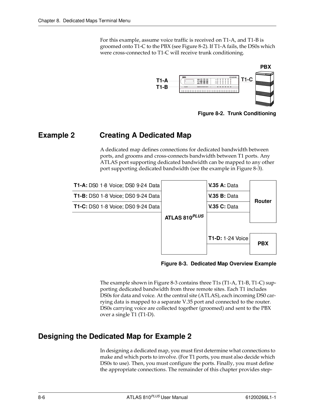
For this example, assume voice traffic is received on T1-A, and T1-B is groomed onto T1-C to the PBX (see Figure 8-2). If T1-A fails, the DS0s which were cross-connected to T1-C will receive trunk conditioning.

T1-A

T1-B

ATLAS 800

PBX

T1-C

Figure 8-2. Trunk Conditioning

Example 2 Creating A Dedicated Map

A dedicated map defines connections for dedicated bandwidth between ports, and grooms and cross-connects bandwidth between T1 ports. Any ATLAS port supporting dedicated bandwidth can be mapped to any other port supporting dedicated bandwidth (see the example in Figure 8-3).

T1-A:DS0 1-8 Voice; DS0 9-24 Data

T1-B:DS0 1-8 Voice; DS0 9-24 Data

T1-C:DS0 1-8 Voice; DS0 9-24 Data

ATLAS 810PLUS

V.35 A: Data

V.35 B: Data

V.35 C: Data

T1-D:1-24 Voice

Router

PBX

Figure 8-3. Dedicated Map Overview Example

The example shown in Figure 8-3contains three T1s (T1-A, T1-B, T1-C) sup- porting dedicated bandwidth from three remote sites. Each T1 includes DS0s for data and voice. At the central site (ATLAS), each incoming DS0 car- rying data is mapped to a separate V.35 port and connected to the router. DS0s carrying voice are collected together (groomed) and sent to the PBX over a single T1 (T1-D).

Designing the Dedicated Map for Example 2

In designing a dedicated map, you must first determine what connections to make and which ports to involve. (For T1 ports, you must also decide which DS0s to use). Then, you must configure the ports. Finally, you must define the appropriate connections. The remainder of this chapter provides step-

8-6

ATLAS 810PLUS User Manual

61200266L1-1

Page 90
Image 90
ADTRAN 810 Plus manual Example 2 Creating a Dedicated Map, Designing the Dedicated Map for Example