Chapter 2. Installation
Option Slots
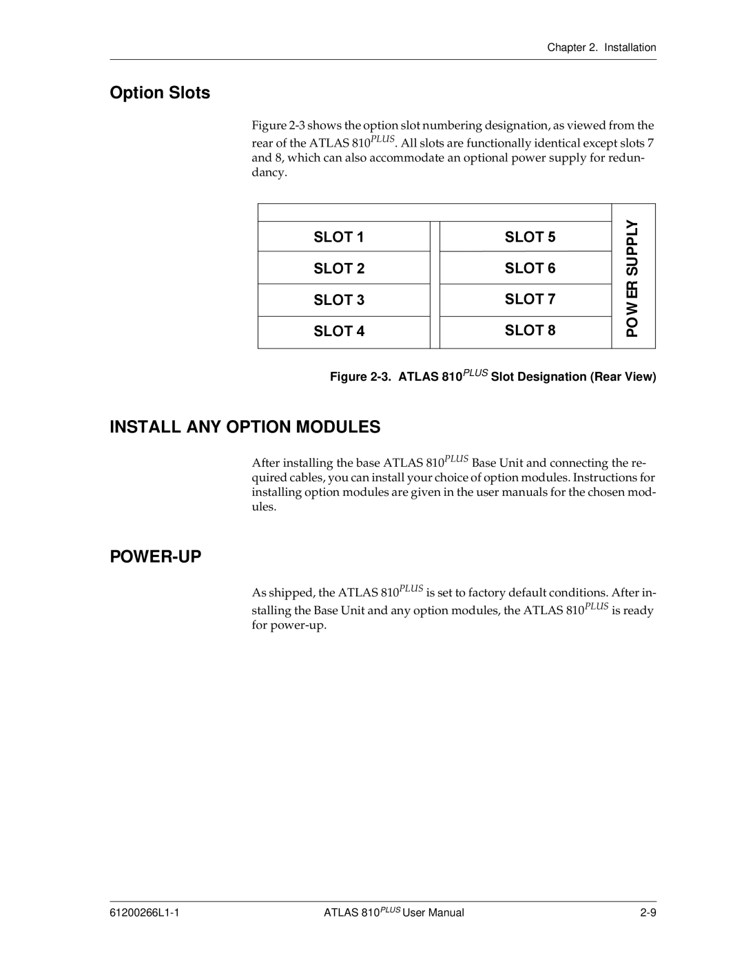
Figure 2-3 shows the option slot numbering designation, as viewed from the
rear of the ATLAS 810PLUS. All slots are functionally identical except slots 7 and 8, which can also accommodate an optional power supply for redun- dancy.
6/27ýì
6/27ýë
6/27ýê
6/27ýé
6/27ýè
6/27ýç
6/27ýæ
6/27ýå
POWER SUPPLY
Figure 2-3. ATLAS 810PLUS Slot Designation (Rear View)
INSTALL ANY OPTION MODULES
After installing the base ATLAS 810PLUS Base Unit and connecting the re- quired cables, you can install your choice of option modules. Instructions for installing option modules are given in the user manuals for the chosen mod- ules.
POWER-UP
As shipped, the ATLAS 810PLUS is set to factory default conditions. After in- stalling the Base Unit and any option modules, the ATLAS 810PLUS is ready for
ATLAS 810PLUS User Manual |