Chapter 2. Installation
|
| Table |
|
|
|
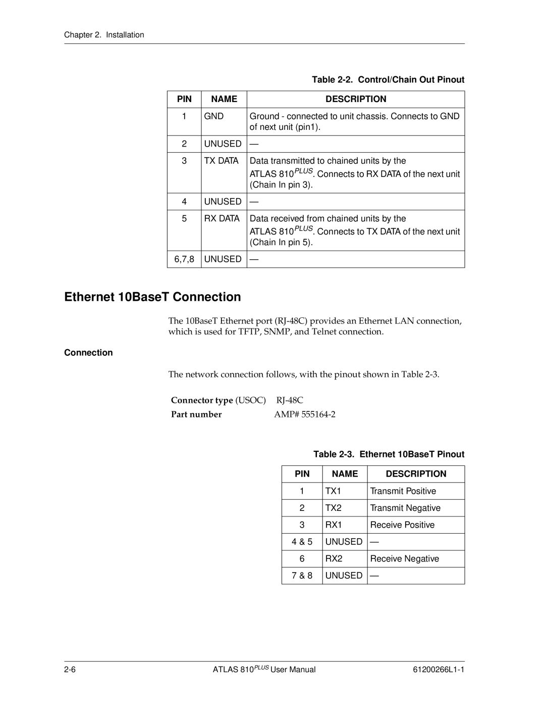
PIN | NAME | DESCRIPTION |
|
|
|
1 | GND | Ground - connected to unit chassis. Connects to GND |
|
| of next unit (pin1). |
|
|
|
2 | UNUSED | — |
|
|
|
3 | TX DATA | Data transmitted to chained units by the |
|
| ATLAS 810PLUS. Connects to RX DATA of the next unit |
|
| (Chain In pin 3). |
|
|
|
4 | UNUSED | — |
|
|
|
5 | RX DATA | Data received from chained units by the |
|
| ATLAS 810PLUS. Connects to TX DATA of the next unit |
|
| (Chain In pin 5). |
|
|
|
6,7,8 | UNUSED | — |
|
|
|
Ethernet 10BaseT Connection
The 10BaseT Ethernet port
Connection
The network connection follows, with the pinout shown in Table
Connector type (USOC) | |
Part number | AMP# |
Table 2-3. Ethernet 10BaseT Pinout
PIN | NAME | DESCRIPTION |
|
|
|
1 | TX1 | Transmit Positive |
|
|
|
2 | TX2 | Transmit Negative |
|
|
|
3 | RX1 | Receive Positive |
|
|
|
4 & 5 | UNUSED | — |
|
|
|
6 | RX2 | Receive Negative |
|
|
|
7 & 8 | UNUSED | — |
|
|
|
ATLAS 810PLUS User Manual |