Chapter 2. Installation
Connection
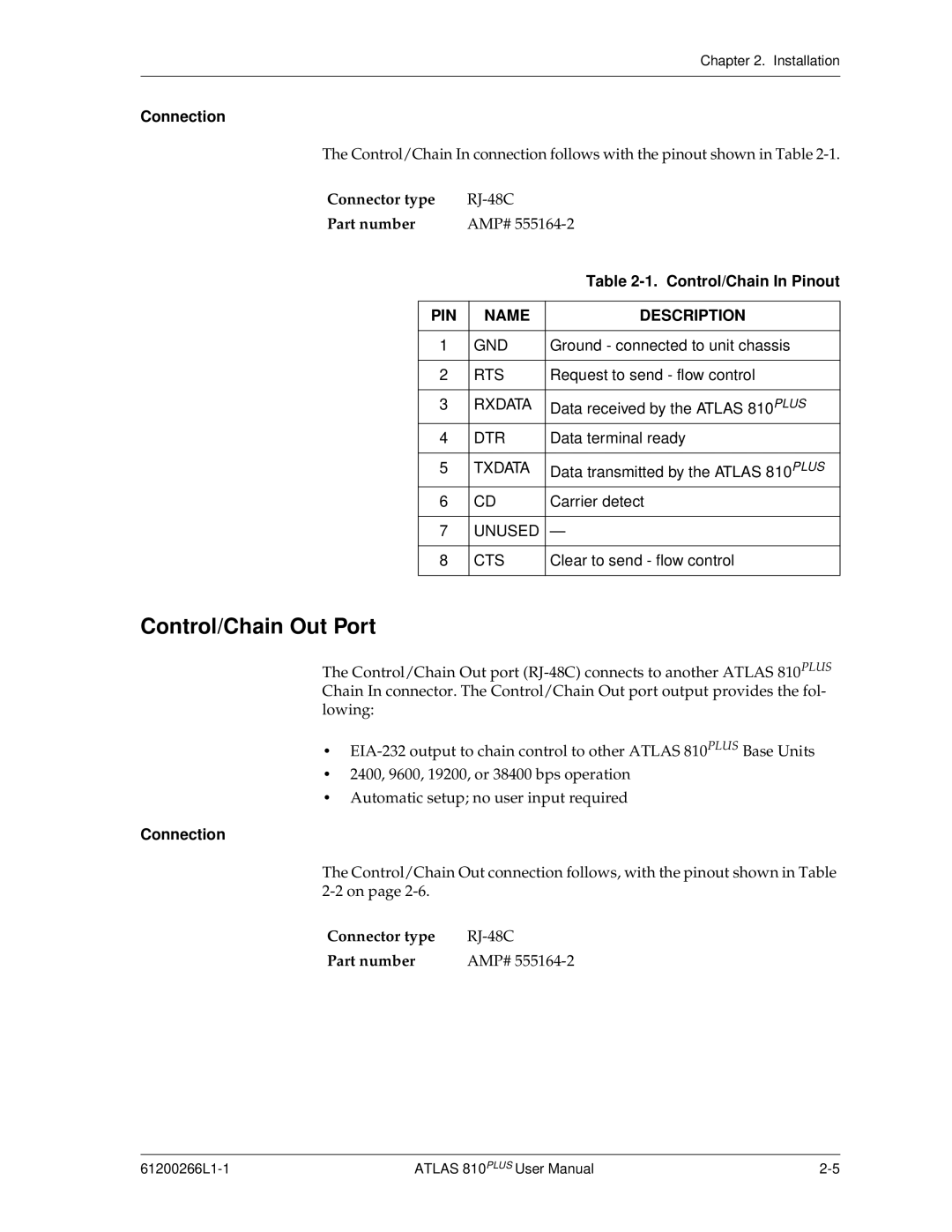
The Control/Chain In connection follows with the pinout shown in Table
Connector type |
| |||
Part number | AMP# | |||
|
|
|
| Table |
|
|
|
|
|
| PIN |
| NAME | DESCRIPTION |
|
|
|
|
|
| 1 |
| GND | Ground - connected to unit chassis |
|
|
|
|
|
| 2 |
| RTS | Request to send - flow control |
|
|
|
|
|
| 3 |
| RXDATA | Data received by the ATLAS 810PLUS |
| 4 |
| DTR | Data terminal ready |
|
|
|
|
|
| 5 |
| TXDATA | Data transmitted by the ATLAS 810PLUS |
| 6 |
| CD | Carrier detect |
|
|
|
|
|
| 7 |
| UNUSED | — |
|
|
|
|
|
| 8 |
| CTS | Clear to send - flow control |
|
|
|
|
|
Control/Chain Out Port
The Control/Chain Out port
•
•2400, 9600, 19200, or 38400 bps operation
•Automatic setup; no user input required
Connection
The Control/Chain Out connection follows, with the pinout shown in Table
Connector type | |
Part number | AMP# |
ATLAS 810PLUS User Manual |