Chapter 2. Installation
A supplementary equipment grounding conductor shall be installed be- tween the product or system and ground that is in addition to the equipment grounding conductor in the power supply cord.
The supplementary equipment grounding conductor shall not be smaller in size than the ungrounded
REVIEW THE REAR PANEL DESIGN
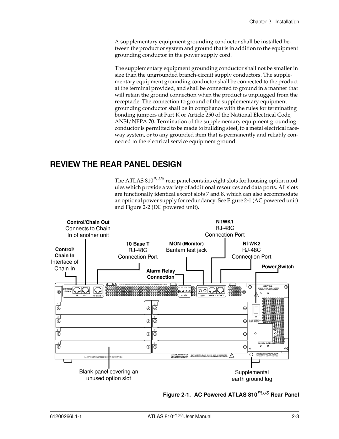
The ATLAS 810PLUS rear panel contains eight slots for housing option mod- ules which provide a variety of additional resources and data ports. All slots are functionally identical except slots 7 and 8, which can also accommodate an optional power supply for redundancy. See Figure
Control/Chain Out | NTWK1 |
Connects to Chain | |
In of another unit | Connection Port |
Control/
Chain In
Interface of
Chain In
CONTROL
/CHAIN
IN OUT
1
2
10 Base T | MON (Monitor) | |
| Bantam test jack | |
Connection Port |
|
|
Alarm Relay |
| |
Connection |
| |
CAUTION: MAINTENANCE TO BE PERFORMED BY TRAINED SERVICE PERSONNEL ONLY |
| |
| NC NO COM GND |
|
10 BASE T | ALARM | MON NTWK 1 NTWK 2 |
5 |
|
|
6 |
|
|
NTWK2
RJ-48C
Connection Port
Power Switch
CAUTION: |
REMOVE POWER CORD PRIOR TO |
REMOVAL OF POWER SUPPLY |
I |
O
3
7
4
8
4A/25OV SLOBLO 


|
|
|
|
|
|
|
| CAUTION: FOR CONTINUED PROTECTION |
|
|
|
|
|
|
|
| |
|
|
|
|
|
|
| ||
|
|
|
|
| SUPPLAMENTAL EARTH GROUND MUST BE CONNECTED |
| AGAINST RISK OF FIRE REPLACE ONLY | |
| ALL EMPTY SLOTS MUST BE COVERED | WITH BLANK PANELS |
|
| ELECTRIC SHOCK | PRIOR TO CONNECTION OF TELECOMMUNICATION WIRING |
| WITH SAME TYPE AND RATING OF FUSE. |
|
|
|
|
|
|
|
|
|
|
|
|
|
|
|
|
|
|
Blank panel covering an | Supplemental |
unused option slot | earth ground lug |
| Figure |
ATLAS 810PLUS User Manual |