Chapter 2. Installation
Network Connection
The two
applicable ANSI and AT&T® standards. The NIs provide the following func- tions:
•AMI or B8ZS coding
•Manual line build out
•D4 or ESF framing
•Network performance monitoring and reporting
•Test loopbacks with QRSS generation and checking
•Extensive
Connection
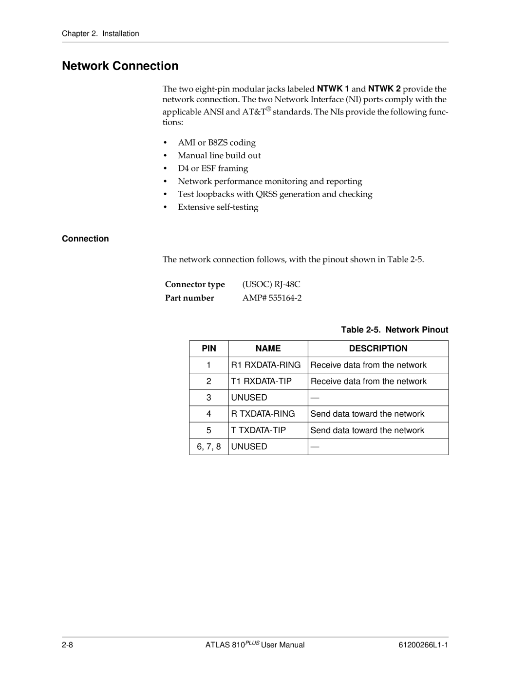
The network connection follows, with the pinout shown in Table
Connector type | (USOC) |
| |
Part number | AMP# |
| |
|
|
| Table |
|
|
|
|
| PIN | NAME | DESCRIPTION |
|
|
|
|
| 1 | R1 | Receive data from the network |
|
|
|
|
| 2 | T1 | Receive data from the network |
|
|
|
|
| 3 | UNUSED | — |
|
|
|
|
| 4 | R | Send data toward the network |
|
|
|
|
| 5 | T | Send data toward the network |
|
|
|
|
| 6, 7, 8 | UNUSED | — |
|
|
|
|
ATLAS 810PLUS User Manual |