Chapter 2. Installation
Alarm Relay Connection
This connection alerts the user when a selected alarm condition exists. The
After the appropriate connections have been made, tighten the screws using a flathead screwdriver before reinserting the terminal block into the rear panel of the ATLAS 810PLUS.
Connection
Table
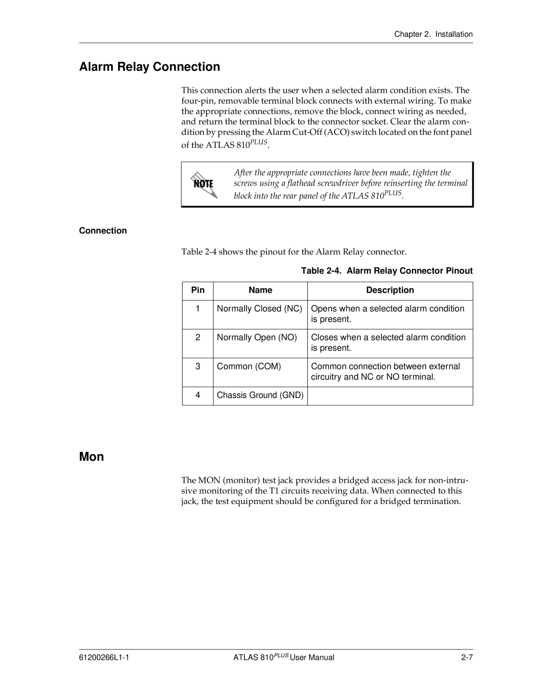
Table 2-4. Alarm Relay Connector Pinout
Pin | Name | Description |
|
|
|
1 | Normally Closed (NC) | Opens when a selected alarm condition |
|
| is present. |
|
|
|
2 | Normally Open (NO) | Closes when a selected alarm condition |
|
| is present. |
|
|
|
3 | Common (COM) | Common connection between external |
|
| circuitry and NC or NO terminal. |
|
|
|
4 | Chassis Ground (GND) |
|
|
|
|
Mon
The MON (monitor) test jack provides a bridged access jack for
ATLAS 810PLUS User Manual |