|
|
|
|
|
|
| 6. PARAMETER DESCRIPTION | |
|
|
|
|
|
|
|
|
|
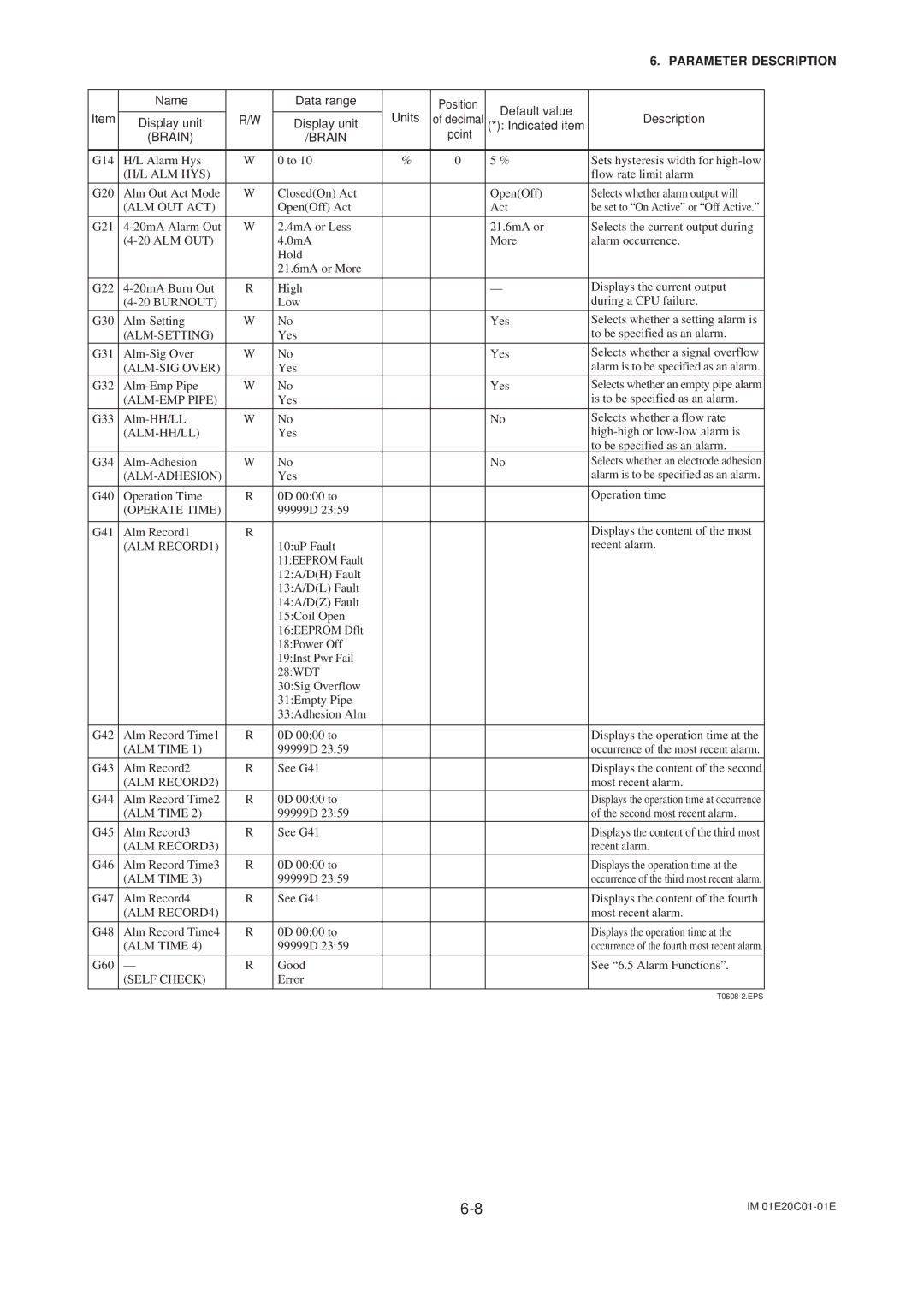
| Name |
| Data range |
| Position | Default value |
|
|
|
|
|
| Units |
|
| ||
Item | Display unit | R/W | Display unit | of decimal | Description |
| ||
(*): Indicated item |
| |||||||
|
| |||||||
| (BRAIN) |
| /BRAIN |
| point |
|
|
|
|
|
|
|
|
|
|
|
|
G14 | H/L Alarm Hys | W | 0 to 10 | % | 0 | 5 % | Sets hysteresis width for |
|
| (H/L ALM HYS) |
|
|
|
|
| flow rate limit alarm |
|
G20 | Alm Out Act Mode | W | Closed(On) Act |
|
| Open(Off) | Selects whether alarm output will |
|
| (ALM OUT ACT) |
| Open(Off) Act |
|
| Act | be set to “On Active” or “Off Active.” |
|
|
|
|
|
|
|
|
|
|
G21 | W | 2.4mA or Less |
|
| 21.6mA or | Selects the current output during |
| |
|
| 4.0mA |
|
| More | alarm occurrence. |
| |
|
|
| Hold |
|
|
|
|
|
|
|
| 21.6mA or More |
|
|
|
|
|
|
|
|
|
|
|
|
|
|
G22 | R | High |
|
| — | Displays the current output |
| |
|
| Low |
|
|
| during a CPU failure. |
| |
G30 | W | No |
|
| Yes | Selects whether a setting alarm is |
| |
|
|
| Yes |
|
|
| to be specified as an alarm. |
|
G31 | W | No |
|
| Yes | Selects whether a signal overflow |
| |
|
|
| Yes |
|
|
| alarm is to be specified as an alarm. |
|
G32 | W | No |
|
| Yes | Selects whether an empty pipe alarm |
| |
|
| Yes |
|
|
| is to be specified as an alarm. |
| |
G33 | W | No |
|
| No | Selects whether a flow rate |
| |
|
|
| Yes |
|
|
|
| |
|
|
|
|
|
|
| to be specified as an alarm. |
|
G34 | W | No |
|
| No | Selects whether an electrode adhesion |
| |
|
| Yes |
|
|
| alarm is to be specified as an alarm. |
| |
|
|
|
|
|
|
|
|
|
G40 | Operation Time | R | 0D 00:00 to |
|
|
| Operation time |
|
| (OPERATE TIME) |
| 99999D 23:59 |
|
|
|
|
|
|
|
|
|
|
|
|
|
|
G41 | Alm Record1 | R |
|
|
|
| Displays the content of the most |
|
| (ALM RECORD1) |
| 10:uP Fault |
|
|
| recent alarm. |
|
|
|
| 11:EEPROM Fault |
|
|
|
|
|
|
|
| 12:A/D(H) Fault |
|
|
|
|
|
|
|
| 13:A/D(L) Fault |
|
|
|
|
|
|
|
| 14:A/D(Z) Fault |
|
|
|
|
|
|
|
| 15:Coil Open |
|
|
|
|
|
|
|
| 16:EEPROM Dflt |
|
|
|
|
|
|
|
| 18:Power Off |
|
|
|
|
|
|
|
| 19:Inst Pwr Fail |
|
|
|
|
|
|
|
| 28:WDT |
|
|
|
|
|
|
|
| 30:Sig Overflow |
|
|
|
|
|
|
|
| 31:Empty Pipe |
|
|
|
|
|
|
|
| 33:Adhesion Alm |
|
|
|
|
|
|
|
|
|
|
|
|
|
|
G42 | Alm Record Time1 | R | 0D 00:00 to |
|
|
| Displays the operation time at the |
|
| (ALM TIME 1) |
| 99999D 23:59 |
|
|
| occurrence of the most recent alarm. |
|
G43 | Alm Record2 | R | See G41 |
|
|
| Displays the content of the second |
|
| (ALM RECORD2) |
|
|
|
|
| most recent alarm. |
|
G44 | Alm Record Time2 | R | 0D 00:00 to |
|
|
| Displays the operation time at occurrence |
|
| (ALM TIME 2) |
| 99999D 23:59 |
|
|
| of the second most recent alarm. |
|
G45 | Alm Record3 | R | See G41 |
|
|
| Displays the content of the third most |
|
| (ALM RECORD3) |
|
|
|
|
| recent alarm. |
|
G46 | Alm Record Time3 | R | 0D 00:00 to |
|
|
| Displays the operation time at the |
|
| (ALM TIME 3) |
| 99999D 23:59 |
|
|
| occurrence of the third most recent alarm. |
|
|
|
|
|
|
|
|
|
|
G47 | Alm Record4 | R | See G41 |
|
|
| Displays the content of the fourth |
|
| (ALM RECORD4) |
|
|
|
|
| most recent alarm. |
|
|
|
|
|
|
|
|
|
|
G48 | Alm Record Time4 | R | 0D 00:00 to |
|
|
| Displays the operation time at the |
|
| (ALM TIME 4) |
| 99999D 23:59 |
|
|
| occurrence of the fourth most recent alarm. |
|
G60 | — | R | Good |
|
|
| See “6.5 Alarm Functions”. |
|
| (SELF CHECK) |
| Error |
|
|
|
|
|
|
|
|
|
|
|
|
|
|
IM |