Output Example 3
The high alarm (H) is set to 80% or more of the flow rate span; the
Settings are:
G10: Low Alarm =
G11: High Alarm = 80%
G12: Low Low Alarm =
G13: High High Alarm = 90%
[%] | High High Alarm | |
100 | ||
| ||
90 |
| |
80 |
| |
| High Alarm | |
| Instantaneous flow rate | |
50 |
| |
0 | Time (t) | |
SO1 | H | |
|
|
|
|
|
| L Alarm set to | |
|
|
|
|
| ||
|
|
|
|
| that the alarm is | |
SO2 |
| HH |
|
| disabled. | |
|
|
|
|
|
| |
|
|
|
|
|
| |
|
|
|
|
| ||
|
|
|
| LL Alarm set to | ||
|
|
|
| that the alarm is disabled. | ||
|
|
|
|
|
|
|
AL
HH
Select “H/L Alarm” forF10: SO1 Function
Select “HH/LL Alarm” forF11: SO2 Function
Select “Closed (On) Act” forF14: SO1/2 Active Mode
Select “Open (Off) Act” forG20: Alm Out Act Mode
Select “Yes” forG33:
F0612.EPS
NOTE
•Although the same items can be selected using the SO1 output terminal (selected for F10) and the SO2 output terminal (selected for F11), output is identical for both.
•Setting values of
6. PARAMETER DESCRIPTION
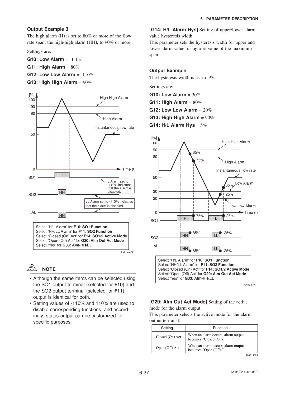
[G14: H/L Alarm Hys] Setting of upper/lower alarm value hysteresis width
This parameter sets the hysteresis width for upper and lower alarm value, using a % value of the maximum span.
Output Example
The hysteresis width is set to 5%.
Settings are:
G10: Low Alarm = 30%
G11: High Alarm = 80%
G12: Low Low Alarm = 20%
G13: High High Alarm = 90%
G14: H/L Alarm Hys = 5%
[%] |
|
|
| High High Alarm |
100 |
|
|
| |
|
|
|
| |
90 |
| 85% |
|
|
80 |
|
|
| |
| 75% |
|
| |
|
|
| High Alarm | |
|
|
|
| |
|
|
| Instantaneous flow rate | |
50 |
|
|
|
|
|
|
|
| 35% Low Alarm |
30 |
|
|
| 25% |
20 |
|
|
| |
|
|
|
| |
|
|
|
| Low Low Alarm |
0 |
| 75% |
| Time (t) |
| H | L | 35% | |
SO1 |
|
| ||
|
|
|
| |
| HH | 85% | LL | 25% |
SO2 |
|
| ||
|
|
|
| |
AL | HH |
| LL |
|
| 85% | 25% | ||
|
|
| ||
Select “H/L Alarm” forF10: SO1 Function
Select “HH/LL Alarm” forF11: SO2 Function
Select “Closed (On) Act” forF14: SO1/2 Active Mode
Select “Open (Off) Act” forG20: Alm Out Act Mode
Select “Yes” forG33:
F0613.EPS
[G20: Alm Out Act Mode] Setting of the active mode for the alarm output.
This parameter selects the active mode for the alarm output terminal.
Setting | Function | |
|
| |
Closed (On) Act | When an alarm occurs, alarm output | |
becomes "Closed (On)." | ||
| ||
|
| |
Open (Off) Act | When an alarm occurs, alarm output | |
becomes "Open (Off)." | ||
| ||
|
|
T0631.EPS
IM |