9AXFA11 :
1.000000
DEL ABORT ENTER
10AXFA11 :
Scaled output: 1.000 equal readout device?
1 Yes
2 No
ABORT ENTER
11AXFA11 :
ABORT OK
12AXFA11 :
5.000000
DEL ABORT ENTER
13AXFA11 :
Scaled output: 5.210 equal readout device?
1 Yes
2 No
ABORT ENTER
14AXFA11 :
OK
15AXFA11 :
1 Auto Zero Exe
2 Magflow Zero
3 D/A Trim
4![]() Scaled D/A trim
Scaled D/A trim
HELP SAVE HOME
‘1.01’
F4
(ENTER)
F4
(ENTER)
F4
(OK)
‘5.21’
F4
(ENTER)
F4
(ENTER)
F4
(OK)
F3
(HOME)
8. OPERATION VIA HART COMMUNICATOR
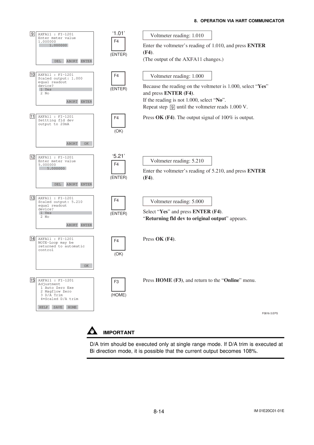
Voltmeter reading: 1.010
Enter the voltmeter’s reading of 1.010, and press ENTER
(F4).
(The output of the AXFA11 changes.)
Voltmeter reading: 1.000
Because the reading on the voltmeter is 1.000, select “Yes” and press ENTER (F4).
If the reading is not 1.000, select “No”.
Repeat step 9 until the voltmeter reads 1.000 V.
Press OK (F4). The output signal of 100% is output.
Voltmeter reading: 5.210
Enter the voltmeter’s reading of 5.210, and press ENTER
(F4).
Voltmeter reading: 5.000
Select “Yes” and press ENTER (F4).
“Returning fld dev to original output” appears.
Press OK (F4).
Press HOME (F3), and return to the “Online” menu.
IMPORTANT
D/A trim should be executed only at single range mode. If D/A trim is executed at Bi direction mode, it is possible that the current output becomes 108%.
IM |