6.4Parameter Description
(1) Menu B: Easy Setup items
Those parameters with a high frequency of use have been grouped together in Easy Setup. All basic functions can be controlled using only the parameters from this block. Parameters from Menu B share identical names with those from other menus; however, modification of one such parameter will result in the other being automatically modified.
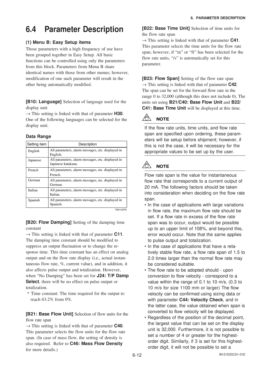
[B10: Language] Selection of language used for the display unit
→This setting is linked with that of parameter H30. One of the following languages can be selected for the display unit.
Data Range
Setting item | Description |
|
|
English | All parameters, alarm messages, etc. displayed in |
| English. |
|
|
Japanese | All parameters, alarm messages, etc. displayed in |
| Japanese katakana. |
|
|
French | All parameters, alarm messages, etc. displayed in |
| French. |
|
|
German | All parameters, alarm messages, etc. displayed in |
| German. |
|
|
Italian | All parameters, alarm messages, etc. displayed in |
| Italian. |
|
|
Spanish | All parameters, alarm messages, etc. displayed in |
| Spanish. |
|
|
| T0614.EPS |
[B20: Flow Damping] Setting of the damping time constant
→This setting is linked with that of parameter C11. The damping time constant should be modified to suppress an output fluctuation or to change the re- sponse time. This time constant has an effect on analog output and on the flow rate display (i.e., actual instan- taneous flow rate, %, current value), and in addition, it also affects pulse output and totalization. However, when “No Damping” has been set for J24: T/P Damp Select, there will be no effect on pulse output or totalization.
*Time constant: The time required for the output to reach 63.2% from 0%.
[B21: Base Flow Unit] Selection of flow units for the flow rate span
→This setting is linked with that of parameter C40. This parameter selects the flow units for the flow rate span. (In case of mass flow, the setting of density is also required. Refer to C46: Mass Flow Density for more details.)
6. PARAMETER DESCRIPTION
[B22: Base Time Unit] Selection of time units for the flow rate span
→This setting is linked with that of parameter C41. This parameter selects the time units for the flow rate span; however, if “m” or “ft” has been selected for the flow rate units, “/s” is automatically set for this parameter.
[B23: Flow Span] Setting of the flow rate span
→This setting is linked with that of parameter C42. The span can be set for the forward flow rate in the range 0 to 32,000 (although this does not include 0). The units set using B21/C40: Base Flow Unit and B22/ C41: Base Time Unit will be displayed at this time.
NOTE
If the flow rate units, time units, and flow rate span are specified upon ordering, these param- eters will be setup before shipment; however, if this is not the case, it will be necessary for the appropriate values to be set up by the user.
NOTE
Flow rate span is the value for instantaneous flow rate that corresponds to a current output of 20 mA. The following factors should be taken into consideration when deciding on the flow rate span.
•In the case of applications with large variations in flow rate, the maximum flow rate should be set. If a flow rate in excess of the flow rate span was to occur, output would be possible up to an upper limit of 108%, and beyond this, error would occur. Note that the same applies to pulse output and totalization.
•In the case of applications that have a rela- tively stable flow rate, a flow rate span of 1.5 to 2.0 times larger than the normal flow rate may be considered suitable.
•The flow rate to be adopted should - upon conversion to flow velocity - correspond to a value within the range of 0.1 to 10 m/s. (0.3 to 10 m/s for size 1100 mm or larger) The flow velocity can be confirmed using sizing data or with parameter C44: Velocity Check, and in the latter case, the value obtained when span is converted to flow velocity will be displayed.
•Regardless of the position of the decimal point, the largest value that can be set on the display unit is 32,000. Furthermore, it is not possible to set a number of 4 or greater for the highest- order digit. Similarly, if 3 is set for this highest- order digit, it will not be possible to set a
IM |