Americas Headquarters
Text Part Number OL-9775-02
Page
N T E N T S
Iii
Assigning the Switch IP Address and Default Gateway
Understanding Cisco Configuration Engine Software
Clustering Switches
Catalyst 1900 and Catalyst 2820 CLI Considerations
Vii
Creating a Banner
Viii
Changing the Default Privilege Level for Lines
Device Roles
Bypass
Routed Ports
Xii
Monitoring and Maintaining the Interfaces
Xiii
Encapsulation Types
Xiv
Domain Names
Private-VLAN Configuration Guidelines
Xvi
Disabled State
Xvii
Boundary Ports
Xviii
Xix
19-25
Dhcp Server
Configuring Dynamic ARP Inspection
Xxi
Configuring MVR
Xxii
Understanding Storm Control
Xxiii
Understanding Udld Modes of Operation
Xxiv
Creating an Rspan Source Session
Xxv
Snmp Agent Functions
Xxvi
Creating a Numbered Extended ACL
Xxvii
Interaction with Other Features and Switches
Xxviii
Xxix
Port-Channel Interfaces
Xxx
Configuring IP Addressing
Xxxi
Nonstop Forwarding Awareness
Xxxii
IPv6 Addresses
Xxxiii
Configuring Hsrp Priority
Xxxiv
Configuring IP Multicast Routing
Xxxv
Configuring Basic Dvmrp Interoperability Features
Xxxvi
Using a Filter
Xxxvii
Xxxviii
45-14
Configuring Online Diagnostics
Xxxix
Unsupported Route-Map Configuration Commands C-1
Hsrp
Xli
VTP
Xlii
Purpose
Preface
Audience
Conventions
Related Publications
Xliv
Xlv
Xlvi
Features
Overview
Deployment Features
Availability and Redundancy Features, Vlan Features,
Overview Features
Performance Features
Management Options
Manageability Features
Availability and Redundancy Features
Vlan Features
Security Features
Overview Features
QoS and CoS Features
Layer 3 Features
Power over Ethernet Features
Vlan
Default Settings After Initial Switch Configuration
Monitoring Features
Overview Default Settings After Initial Switch Configuration
Overview Default Settings After Initial Switch Configuration
Network Configuration Examples
Design Concepts for Using the Switch
Network Demands Suggested Design Methods
Cost-Effective Wiring Closet
High-Performance Wiring Closet
High-Performance Workgroup Gigabit-to-the-Desktop
Redundant Gigabit Backbone
Server Aggregation
Linux Server Cluster
Cisco SoftPhone Software Gigabit servers
Internet Cisco 2600 or 3700 routers Catalyst 3560-E switches
Large Network Using Catalyst 3750-E and 3560-E Switches
Cisco 7x00 routers Catalyst
Catalyst 3560-E
Multidwelling Network Using Catalyst 3750-E Switches
Long-Distance, High-Bandwidth Transport Configuration
11 Catalyst 3750-E Switches in a MAN Configuration
Where to Go Next
Access layer Aggregation layer
OL-9775-02
Using the Command-Line Interface
Understanding Command Modes
Quit
Mode Access Method Prompt Exit Method About This Mode
Configure
Ctrl-Z
Understanding the Help System
Console command
Command Purpose
Line vty or line
Command ?
Understanding Abbreviated Commands
Understanding no and default Forms of Commands
Command keyword ?
Error Message Meaning How to Get Help
Understanding CLI Error Messages
Using Configuration Logging
Recalling Commands
Using Command History
Changing the Command History Buffer Size
Action1 Result
Enabling and Disabling Editing Features
Using Editing Features
Disabling the Command History Feature
Switch# terminal editing
Editing Commands through Keystrokes
Capability Keystroke1 Purpose
Press Ctrl-L or Ctrl-R
Editing Command Lines that Wrap
Return and Space bar
Switch# show interfaces include protocol
Accessing the CLI
Command begin include exclude regular-expression
Using the Command-Line Interface Accessing the CLI
OL-9775-02
Assigning the Switch IP Address and Default Gateway
Understanding the Boot Process
Assigning Switch Information
Feature Default Setting
Default Switch Information
Understanding DHCP-Based Autoconfiguration
Dhcp Client Request Process
Dhcp Client and Server Message Exchange
Configuring DHCP-Based Autoconfiguration
Dhcp Server Configuration Guidelines
Configuring the Tftp Server
Configuring the DNS
Routerconfig-if#ip helper-address
Configuring the Relay Device
Obtaining Configuration Files
Example Configuration
Tftpserver
Tftp Server Configuration on Unix
Switch a Switch B Switch C Switch D
DNS Server Configuration
Dhcp Client Configuration
Manually Assigning IP Information
Switch# copy running-config startup-config
Checking and Saving the Running Configuration
Switch# show running-config
Automatically Downloading a Configuration File
Modifying the Startup Configuration
Default Boot Configuration
Show boot
Booting Manually
Boot config-file flash/ file-url
Configure terminal Enter global configuration mode
Booting a Specific Software Image
Boot system filesystem /file-url
Boot system switch number all
Controlling Environment Variables
Switch current-stack-member-number renumber
Set Manualboot yes Boot manual
Set Switchnumber
Set Switchpriority
Variable Description
Configuring a Scheduled Reload
Scheduling a Reload of the Software Image
Reload in hhmm text
Displaying Scheduled Reload Information
Switch# reload at
Switch# reload at 0200 jun
Configuring Cisco IOS CNS Agents
Understanding Cisco Configuration Engine Software
Configuration Service
Configuration Engine Architectural Overview
What You Should Know About the CNS IDs and Device Hostnames
Event Service
ConfigID
NameSpace Mapper
Hostname and DeviceID
Using Hostname, DeviceID, and ConfigID
DeviceID
Initial Configuration
Understanding Cisco IOS Agents
Synchronized Configuration
Configuring Cisco IOS Agents
Incremental Partial Configuration
Enabling Automated CNS Configuration
Device Required Configuration
Enabling the CNS Event Agent
Backup init-retry retry-count keepalive seconds
Show running-config
Show cns event connections
Enabling an Initial Configuration
Enabling the Cisco IOS CNS Agent
Mac-address event
Cns config initial ip-address hostname
Cns id interface num dns-reverse ipaddress
Cns id hardware-serial hostname string string
Cns config partial ip-address hostname
Enabling a Partial Configuration
Show running-config Verify your entries
Show cns config stats
Show cns event stats
Displaying CNS Configuration
Show cns config connections
Show cns event subject
Managing Switch Stacks
Understanding Switch Stacks
Managing Switch Stacks Understanding Switch Stacks
Switch Stack Membership
Creating a Switch Stack from Two Standalone Switches
Adding a Standalone Switch to a Switch Stack
Stack Master Election and Re-Election
Switch Stack Bridge ID and Router MAC Address
Stack Member Numbers
Stack Member Priority Values
Scenario Result
Switch Stack Offline Configuration
Effects of Adding a Provisioned Switch to a Switch Stack
Scenario Result
Switch Stack Software Compatibility Recommendations
Effects of Replacing a Provisioned Switch in a Switch Stack
Stack Protocol Version Compatibility
Major Version Number Incompatibility Among Switches
Minor Version Number Incompatibility Among Switches
Understanding Auto-Upgrade and Auto-Advise
Directory
Auto-Upgrade and Auto-Advise Example Messages
Switch
Mar 1 000422.537%IMAGEMGR-6-AUTOADVISESW
Incompatible Software and Stack Member Image Upgrades
Switch Stack Configuration Files
Switch Stack Management Connectivity
Connectivity to Specific Stack Members
Connectivity to the Switch Stack Through an IP Address
Connectivity to the Switch Stack Through an SSH Session
Priority new-priority-number global
Switch Stack Configuration Scenarios
Use the switch stack-member-number
Current-stack-member-number Renumber new-stack-member-number
Enabling Persistent MAC Address
Configuring the Switch Stack
Default Switch Stack Configuration
Switchconfig# stack-mac persistent timer
Stack-mac persistent timer
Show switch
Time-value
Assigning a Stack Member Number
Setting the Stack Member Priority Value
Assigning Stack Member Information
Provisioning a New Member for a Switch Stack
Command Description
Accessing the CLI of a Specific Stack Member
Displaying Switch Stack Information
Show switch stack-member-number
Detail
Show switch stack-ports
Show switch stack-ring activity
OL-9775-02
Clustering Switches
Understanding Switch Clusters
Switch Cisco IOS Release Cluster Capability
Cluster Command Switch Characteristics
Standby Cluster Command Switch Characteristics
Planning a Switch Cluster
Candidate Switch and Cluster Member Switch Characteristics
Automatic Discovery of Cluster Candidates and Members
Discovery Through CDP Hops
Discovery Through CDP Hops
Discovery Through Different VLANs
Discovery Through Different Management VLANs
Discovery Through Different VLANs
Discovery Through Routed Ports
Discovery of Newly Installed Switches
New out-of-box
Hsrp and Standby Cluster Command Switches
Virtual IP Addresses
Other Considerations for Cluster Standby Groups
Automatic Recovery of Cluster Configuration
IP Addresses
Hostnames
Passwords
Snmp Community Strings
Members Other cluster member switches
Switch Clusters and Switch Stacks
Switch Stack Switch Cluster
TACACS+ and Radius
LRE Profiles
Catalyst 1900 and Catalyst 2820 CLI Considerations
Using the CLI to Manage Switch Clusters
Switch# rcommand
Using Snmp to Manage Switch Clusters
Snmp Management for a Cluster
OL-9775-02
Understanding the System Clock
Administering the Switch
Managing the System Time and Date
Understanding Network Time Protocol
NTP
Configuring NTP
Typical NTP Network Configuration
Ntp authenticate
Default NTP Configuration
Configuring NTP Authentication
Configuring NTP Associations
Ntp peer ip-address version number
Configuring NTP Broadcast Service
Switchconfig# ntp server 172.16.22.44 version
Key keyid source interface prefer
Destination-address
Interface interface-id
Ntp broadcast version number key keyid
Ntp broadcast client
Ntp access-group query-only
Configuring NTP Access Restrictions
Ntp broadcastdelay microseconds
Serve-onl y serve peer
Command Purpose
Configuring the Source IP Address for NTP Packets
Interface interface-id
Setting the System Clock
Configuring Time and Date Manually
Displaying the NTP Configuration
Fundamentals Command Reference, Release
Clock timezone zone hours-offset
Displaying the Time and Date Configuration
Configuring the Time Zone
Minutes-offset
Week day month hh mm week day month
Configuring Summer Time Daylight Saving Time
Clock summer-time zone recurring
Hh mm offset
Clock summer-time zone date date
Configuring a System Name and Prompt
Clock summer-time zone date month
Copy running-config startup-confi g
Default System Name and Prompt Configuration
Configuring a System Name
Understanding DNS
Ip domain-name name
Default DNS Configuration
Setting Up DNS
Ip name-server server-address1
Creating a Banner
Default Banner Configuration
Displaying the DNS Configuration
Unix telnet
Configuring a Message-of-the-Day Login Banner
Banner motd c message c
Managing the MAC Address Table
Configuring a Login Banner
Banner login c message c
Building the Address Table
MAC Addresses and VLANs
Changing the Address Aging Time
MAC Addresses and Switch Stacks
Default MAC Address Table Configuration
Mac address-table aging-time
Configuring MAC Address Notification Traps
Removing Dynamic Address Entries
Show mac address-table aging-time
Snmp-server host host-addr traps informs version
String by using the snmp-server community
Snmp-server enable traps mac-notification
Mac address-table notification
Adding and Removing Static Address Entries
Vlan vlan-id interface interface-id
Configuring Unicast MAC Address Filtering
Mac address-table static mac-addr
Show mac address-table static
Vlan vlan-id drop
Managing the ARP Table
Displaying Address Table Entries
OL-9775-02
Configuring SDM Templates
Understanding the SDM Templates
Resource Access Default Routing
Dual IPv4 and IPv6 SDM Templates
SDM Templates and Switch Stacks
IPv4-and-IPv6 Resource Default Routing
SDM Template Configuration Guidelines
Configuring the Switch SDM Template
Default SDM Template
Dual-ipv4-and-ipv6 default routing
Setting the SDM Template
Sdm prefer access default
Vlan routing vlan
Displaying the SDM Templates
Switchconfig# sdm prefer routing
Switchconfig# sdm prefer dual-ipv4-and-ipv6 default
Policy based routing aces 25K
OL-9775-02
Configuring Switch-Based Authentication
Preventing Unauthorized Access to Your Switch
Protecting Access to Privileged Exec Commands
Default Password and Privilege Level Configuration
Switchconfig# enable password l1u2c3k4y5
Setting or Changing a Static Enable Password
Enable password password
Enable secret level level password
Enable password level level password
Encryption-type encrypted-password
Service password-encryption
Show version
Disabling Password Recovery
No service password-recovery
Password password
Setting a Telnet Password for a Terminal Line
Configuring Username and Password Pairs
Switchconfig-line#password let45me67in89
Login local
Configuring Multiple Privilege Levels
Username command
Username name privilege level
Show privilege
Setting the Privilege Level for a Command
Privilege mode level level command
Logging into and Exiting a Privilege Level
Changing the Default Privilege Level for Lines
Command
Controlling Switch Access with TACACS+
Understanding TACACS+
Typical TACACS+ Network Configuration
Configuring TACACS+
TACACS+ Operation
Aaa new-model
Default TACACS+ Configuration
Tacacs-server host hostname port
Aaa group server tacacs+ group-name
Show tacacs Verify your entries
Configuring TACACS+ Login Authentication
Aaa new-model Enable AAA
Authentication login command
Aaa authentication login default
Login authentication default
Line console tty vty line-number
Show running-config Verify your entries
Starting TACACS+ Accounting
Controlling Switch Access with Radius
Displaying the TACACS+ Configuration
Understanding Radius
Transitioning from Radius to TACACS+ Services
Radius Operation
Identifying the Radius Server Host
Configuring Radius
Default Radius Configuration
Page
Ip-address auth-port port-number
Acct-port port-number timeout
Radius-server host hostname
Seconds retransmit retries key
Configuring Radius Login Authentication
Switchconfig# radius-server host host1
Server Host section on
Defining AAA Server Groups
Aaa group server radius group-name
Aaa authorization network radius
Radius
Starting Radius Accounting
Radius-server key string
Configuring Settings for All Radius Servers
Radius-server timeout seconds
Radius-server retransmit retries
Cisco-avpair=shellpriv-lvl=15
Authentication
Radius-server vsa send accounting
Cisco-avpair=ipoutacl#2=deny ip 10.10.10.10 0.0.255.255 any
Radius-server host hostname ip-address non-standard
Controlling Switch Access with Kerberos
Displaying the Radius Configuration
Understanding Kerberos
Term Definition
KDC
Keytab
Authenticating to a Boundary Switch
Kerberos Operation
Srvtab
Obtaining a TGT from a KDC
Configuring Kerberos
Authenticating to Network Services
Aaa authorization network local
Aaa authentication login default local
Aaa authorization exec local
Username name privilege level
Configuring the Switch for Secure Shell
Username command
Understanding SSH
SSH Servers, Integrated Clients, and Supported Versions
Limitations
Configuring SSH
Configuration Guidelines
Setting Up the Switch to Run SSH
Ip ssh timeout seconds
Displaying the SSH Configuration and Status
Configuring the SSH Server
Authentication-retries number
Certificate Authority Trustpoints
Configuring the Switch for Secure Socket Layer Http
Understanding Secure Http Servers and Clients
Rsakeypair TP-self-signed-3080755072
CipherSuites
Configuring Secure Http Servers and Clients
Default SSL Configuration
SSL Configuration Guidelines
Configuring a CA Trustpoint
Configuring the Secure Http Server
Show ip http server secure status
Configuring the Secure Http Client
Ip http timeout-policy idle seconds life
Ip http client secure-trustpoint name
Ip http client secure-ciphersuite
Configuring the Switch for Secure Copy Protocol
Displaying Secure Http Server and Client Status
Show ip http client secure status
Information About Secure Copy
Html
OL-9775-02
10-1
Configuring Ieee 802.1x Port-Based Authentication
Understanding Ieee 802.1x Port-Based Authentication
Device Roles
10-2
Authentication Process
10-3
Authentication Flowchart
10-4
Authentication Initiation and Message Exchange
10-5
10-6
EAPOL-Start
10-7
Ieee 802.1x Authentication and Switch Stacks
Ports in Authorized and Unauthorized States
Ieee 802.1x Host Mode
10-8
Attribute Number AV Pair Name
Ieee 802.1x Accounting
Ieee 802.1x Accounting Attribute-Value Pairs
10-9
Using Ieee 802.1x Authentication with Vlan Assignment
10-10
Using Ieee 802.1x Authentication with Per-User ACLs
10-11
Using Ieee 802.1x Authentication with Guest Vlan
10-12
Using Ieee 802.1x Authentication with Restricted Vlan
10-13
10-14
Using Ieee 802.1x Authentication with Voice Vlan Ports
10-15
Using Ieee 802.1x Authentication with Port Security
10-16
Using Ieee 802.1x Authentication with Wake-on-LAN
10-17
10-18
10-19
Using Multidomain Authentication
Network Admission Control Layer 2 Ieee 802.1x Validation
10-20
Using Web Authentication
For example
Configuring Ieee 802.1x Authentication
10-21
10-22
Default Ieee 802.1x Authentication Configuration
AAA
10-23
Ieee 802.1x Authentication Configuration Guidelines
Ieee 802.1x Authentication
10-24
10-25
Configuring Ieee 802.1x Authentication
MAC Authentication Bypass
Configuring the Switch-to-RADIUS-Server Communication
10-26
Ip-address auth-port port-number key
10-27
Multi-domain
Configuring the Host Mode
Dot1x host-mode multi-host
Show dot1x interface interface-id
10-29
Configuring Periodic Re-Authentication
Manually Re-Authenticating a Client Connected to a Port
Changing the Quiet Period
Changing the Switch-to-Client Retransmission Time
Dot1x timeout tx-period seconds
Show dot1x interface interface-id Verify your entries
Show dot1xinterface interface-id Verify your entries
Setting the Switch-to-Client Frame-Retransmission Number
Switchconfig-if#dot1x timeout tx-period
Dot1x max-reauth-req count
Switchconfig-if#dot1x max-reauth-req
Setting the Re-Authentication Number
Configuring Ieee 802.1x Accounting
10-32
Configuring a Guest Vlan
10-33
Switchconfig# interface gigabitethernet2/0/2
Configuring a Restricted Vlan
Switchport mode private-vlan host
Dot1x guest-vlan vlan-id
Attempts
Dot1x auth-fail vlan vlan-id
Dot1x auth-fail max-attempts max
10-35
Radius-server dead-criteria time time
Configuring the Inaccessible Authentication Bypass Feature
Switchconfig-if#dot1x auth-fail max-attempts
Tries tries
10-37
Reinitialize vlan vlan-id
Configuring Ieee 802.1x Authentication with WoL
Dot1x critical recovery action
Show dot1x interface interface-id
Switchconfig-if#dot1x mac-auth-bypass
Configuring MAC Authentication Bypass
Switchconfig-if#dot1x control-direction both
Dot1x control-direction both
Configuring NAC Layer 2 Ieee 802.1x Validation
10-40
Configuring Web Authentication
10-41
10-42
Dot1x fallback fallback-profile
Disabling Ieee 802.1x Authentication on the Port
No dot1x pae Disable Ieee 802.1x authentication on the port
10-43
Displaying Ieee 802.1x Statistics and Status
10-44
11-1
Configuring Interface Characteristics
Understanding Interface Types
11-2
Switch Ports
Port-Based VLANs
11-3
Access Ports
Trunk Ports
11-4
Routed Ports
Tunnel Ports
11-5
Switch Virtual Interfaces
EtherChannel Port Groups
Supported Protocols and Standards
Power over Ethernet Ports
Gigabit Ethernet Interfaces
11-6
11-7
Powered-Device Detection and Initial Power Allocation
Class
Power Management Modes
11-8
Power Monitoring and Power Policing
11-9
Maximum Power Allocation Cutoff Power on a PoE Port
11-10
Connecting Interfaces
11-11
Ethernet Management Port
11-12
Connecting a Switch Stack to a PC
11-13
Tftp
11-14
Mgmtshow
Using Interface Configuration Mode
Mgmtinit
Mgmtclr
Procedures for Configuring Interfaces
11-16
Macroname
Configuring a Range of Interfaces
Interface range port-range macro
Show interfaces interface-id
11-18
Define interface-range macroname
Configuring and Using Interface Range Macros
Show running-config include define
Interface range macro macroname
Switch# show run include define
Configuring Ethernet Interfaces
Switch# show running-config include define
11-20
Default Ethernet Interface Configuration
11-21
11-22
Configuring Interface Speed and Duplex Mode
Speed and Duplex Configuration Guidelines
Nonegotiate
Setting the Interface Speed and Duplex Parameters
Speed 10 100 1000 auto 10
Duplex auto full half
11-24
Configuring Ieee 802.3x Flow Control
Flowcontrol receive on off desired
With Correct Cabling
Configuring Auto-MDIX on an Interface
Local Side Auto-MDIX
11-25
11-26
Configuring a Power Management Mode on a PoE Port
Interface-id phy
Show power inline i nterface-id
Budgeting Power for Devices Connected to a PoE Port
Power inline auto max max-wattage
Neve r static max max-wattage
Wattage
11-28
Configuring Power Policing
11-29
Adding a Description for an Interface
11-30
Switch# show interfaces gigabitethernet1/0/2 description
Configuring Layer 3 Interfaces
Configuring Ethernet Management Ports
11-31
No shutdown
No switchport
Interface gigabitethernet interface-id vlan vlan-id
11-32
Configuring the System MTU
11-33
System mtu routing bytes
Use the system mtu jumbo Use the system mtu routing
System mtu jumbo bytes
11-34
Reload
Configuring the Cisco Redundant Power System
System mtu bytes
Show system mtu
Standby
Power rps switch-number name string serialnumber
Power rps switch-number port rps-port-id mode active
11-36
Show env power
Configuring the Power Supplies
Power supply switch-numberoff on
Show env rps
11-38
Monitoring and Maintaining the Interfaces
Monitoring Interface Status
Clearing and Resetting Interfaces and Counters
11-39
Shutdown
Shutting Down and Restarting the Interface
Interface vlan vlan-id gigabitethernet interface-id
11-40
12-1
Configuring Smartports Macros
Understanding Smartports Macros
Macro Name Description
Configuring Smartports Macros
Default Smartports Macro Configuration
12-2
Smartports Macro Configuration Guidelines
12-3
Name Sample-Macro and macro name sample-macro will result
Creating Smartports Macros
Macro name macro-name
Show parser macro name macro-name
Applying Smartports Macros
12-5
Show parser macro macro-name
Applying Cisco-Default Smartports Macros
Show parser macro
12-6
12-7
Switch# show parser macro cisco-desktop
Switchconfig-if#macro apply cisco-desktop $AVID
Show parser macro description interface
Displaying Smartports Macros
Show parser macro brief
12-8
13-1
Configuring VLANs
Understanding VLANs
13-2
13-3
Supported VLANs
Vlan Port Membership Modes
Configuring Normal-Range VLANs
13-4
Vlan ID
13-5
13-6
Normal-Range Vlan Configuration Guidelines
Token Ring VLANs
Vlan Configuration in config-vlan Mode
Vlan Configuration Mode Options
Saving Vlan Configuration
Vlan Configuration in Vlan Database Configuration Mode
VLANxxxx, where
Default Ethernet Vlan Configuration
Parameter Default Range
13-8
Remote-span
Copy running-config startup config
Creating or Modifying an Ethernet Vlan
13-9
13-10
Deleting a Vlan
Vlan database
No vlan vlan-id
Assigning Static-Access Ports to a Vlan
Switchport access vlan vlan-id
Show vlan brief
Show interfaces interface-id switchport
Configuring Extended-Range VLANs
Default Vlan Configuration
Vlan fields of the display
Extended-Range Vlan Configuration Guidelines
13-13
Show vlan id vlan-id
Vtp mode transparent
Creating an Extended-Range Vlan
13-14
Creating an Extended-Range Vlan with an Internal Vlan ID
Switchconfig# vtp mode transparent
Switch# copy running-config startup config
Show vlan internal usage
Displaying VLANs
Configuring Vlan Trunks
Command Command Mode Purpose
Trunking Overview
Switches in an ISL Trunking Environment
13-17
Encapsulation Function
Mode Function
Encapsulation Types
13-18
Ieee 802.1Q Configuration Considerations
Default Layer 2 Ethernet Interface Vlan Configuration
Configuring an Ethernet Interface as a Trunk Port
13-19
Dot1q negotiate
Interaction with Other Features
Configuring a Trunk Port
13-20
Defining the Allowed VLANs on a Trunk
13-21
All except remove vlan-list
Switchport trunk allowed vlan add
Changing the Pruning-Eligible List
13-22
Except none remove vlan-list
Configuring the Native Vlan for Untagged Traffic
Switchport trunk pruning vlan add
Vlan ,vlan
Switchport trunk native vlan vlan-id
Configuring Trunk Ports for Load Sharing
Load Sharing Using STP Port Priorities
13-24
13-25
Connect to the trunk ports configured on Switch a
Load Sharing Using STP Path Cost
Or switch stack
Exit Return to global configuration mode
Isl dot1q negotiate
Switchport trunk encapsulation
Interface gigabitethernet1/0/1
Spanning-tree vlan 2-4 cost
13-28
Configuring Vmps
Understanding Vmps
Dynamic-Access Port Vlan Membership
Default Vmps Client Configuration
Vmps Configuration Guidelines
13-29
13-30
Configuring the Vmps Client
Entering the IP Address of the Vmps
Reconfirming Vlan Memberships
Configuring Dynamic-Access Ports on Vmps Clients
Switchport access vlan dynamic
Vmps reconfirm
Vmps reconfirm minutes
Changing the Reconfirmation Interval
Changing the Retry Count
13-32
Switch# show vmps
Troubleshooting Dynamic-Access Port Vlan Membership
Vmps Configuration Example
Monitoring the Vmps
Dynamic Port Vlan Membership Configuration
13-34
14-1
Configuring VTP
Understanding VTP
VTP Domain
14-2
VTP Advertisements
VTP Mode Description
VTP Modes
14-3
14-4
VTP Version
VTP Pruning
14-5
Vlan
14-6
Configuring VTP
VTP and Switch Stacks
VTP Configuration in Global Configuration Mode
Default VTP Configuration
VTP Configuration Options
14-7
Passwords
VTP Configuration Guidelines
VTP Configuration in Vlan Database Configuration Mode
Domain Names
VTP Version
Configuring a VTP Server
Configuration Requirements
14-9
Show vtp status
Vtp password password
Vtp password password
Vtp server
Switch# vlan database
Configuring a VTP Client
Vtp mode client
14-11
Disabling VTP VTP Transparent Mode
14-12
14-13
Enabling VTP Version
Vtp version
Vtp pruning
Adding a VTP Client Switch to a VTP Domain
Enabling VTP Pruning
14-14
14-15
Monitoring VTP
14-16
15-1
Configuring Voice Vlan
Understanding Voice Vlan
15-2
Cisco IP Phone Voice Traffic
Cisco IP Phone Data Traffic
Voice Vlan Configuration Guidelines
Configuring Voice Vlan
Default Voice Vlan Configuration
15-3
Configuring a Port Connected to a Cisco 7960 IP Phone
15-4
Configuring Cisco IP Phone Voice Traffic
15-5
Configuring the Priority of Incoming Data Frames
15-6
Displaying Voice Vlan
15-7
15-8
16-1
Configuring Private VLANs
Understanding Private VLANs
16-2
Private-VLAN Domain
IP Addressing Scheme with Private VLANs
16-3
16-4
Private VLANs across Multiple Switches
Private-VLAN Interaction with Other Features
16-5
Private VLANs and Unicast, Broadcast, and Multicast Traffic
Private VLANs and SVIs
Private VLANs and Switch Stacks
Configuring Private VLANs
Tasks for Configuring Private VLANs
16-6
Secondary and Primary Vlan Configuration
Default Private-VLAN Configuration
Private-VLAN Configuration Guidelines
16-7
Private-VLAN Port Configuration
16-8
Limitations with Other Features
16-9
Configuring and Associating VLANs in a Private Vlan
16-10
16-11
Show vlan private-vlan type
Show interfaces status
Switch# show interfaces gigabitethernet1/0/22 switchport
Configuring a Layer 2 Interface as a Private-VLAN Host Port
Switchport private-vlan host-association
Primaryvlanid secondaryvlanid
Add remove secondaryvlanlist
Switchport mode private-vlan promiscuous
Switchport private-vlan mapping primaryvlanid
16-13
Private-vlan mapping add remove
Switch# show interfaces private-vlan mapping
Interface vlan primaryvlanid
Show interface private-vlan mapping
Monitoring Private VLANs
16-15
16-16
17-1
Configuring Ieee 802.1Q and Layer 2 Protocol Tunneling
Understanding Ieee 802.1Q Tunneling
Ieee 802.1Q Tunnel Ports in a Service-Provider Network
17-2
17-3
Ieee 802.1Q Tunneling Configuration Guidelines
Configuring Ieee 802.1Q Tunneling
Default Ieee 802.1Q Tunneling Configuration
Native VLANs
System MTU
17-5
Ieee 802.1Q Tunneling and Other Features
17-6
Show dot1q-tunnel
Configuring an Ieee 802.1Q Tunneling Port
Vlan dot1q tag native
Show vlan dot1q tag native
Understanding Layer 2 Protocol Tunneling
17-8
17-9
Layer 2 Protocol Tunneling
Configuring Layer 2 Protocol Tunneling
17-10
Default Layer 2 Protocol Tunneling Configuration
17-11
Layer 2 Protocol Tunneling Configuration Guidelines
17-12
Configuring Layer 2 Protocol Tunneling
17-13
L2protocol-tunnel point-to-point
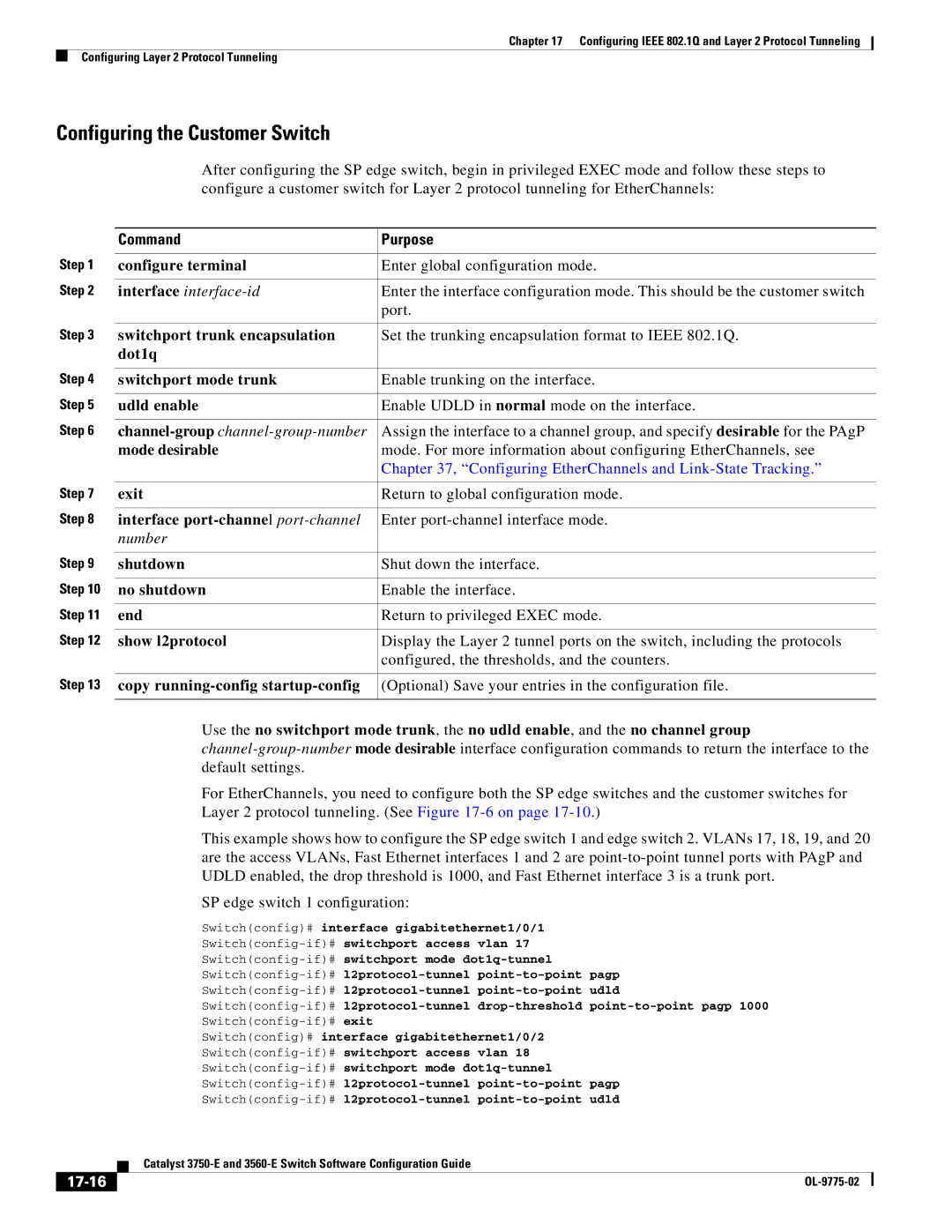
Configuring Layer 2 Tunneling for EtherChannels
Configuring the SP Edge Switch
Pagp lacp udld
17-15
Configuring the Customer Switch
17-16
17-17
Switchconfig-if#channel-group 1 mode desirable
Switchconfig# interface port-channel
Monitoring and Maintaining Tunneling Status
17-18
18-1
Configuring STP
Understanding Spanning-Tree Features
STP Overview
18-2
Spanning-Tree Topology and BPDUs
18-3
Bridge ID, Switch Priority, and Extended System ID
18-4
Bit
Switch Priority Value
Spanning-Tree Interface States
32768 16384 8192 4096 2048 1024 512 256 128
2illustrates how an interface moves through the states
18-6
Learning State
Blocking State
Listening State
Forwarding State
18-8
How a Switch or Port Becomes the Root Switch or Root Port
Disabled State
Accelerated Aging to Retain Connectivity
Spanning Tree and Redundant Connectivity
Spanning-Tree Address Management
18-9
18-10
Spanning-Tree Modes and Protocols
Supported Spanning-Tree Instances
VLAN-Bridge Spanning Tree
Spanning-Tree Interoperability and Backward Compatibility
STP and Ieee 802.1Q Trunks
Rapid PVST+
18-12
Configuring Spanning-Tree Features
Spanning Tree and Switch Stacks
18-13
Default Spanning-Tree Configuration
Spanning-Tree Configuration Guidelines
18-14
Changing the Spanning-Tree Mode
18-15
Show spanning-tree vlan vlan-id Verify your entries
Configuring the Root Switch
Disabling Spanning Tree
18-16
Show spanning-tree detail
Spanning-tree vlan vlan-id root primary
Diameter net-diameter hello-time seconds
18-17
Spanning-tree vlan vlan-id root secondary
Configuring a Secondary Root Switch
Configuring Port Priority
Diameter net-diameter hello-time
Show spanning-tree interface interface-id
Spanning-tree port-priority priority
Spanning-tree vlan vlan-id port-priority priority
Show spanning-tree vlan vlan-id
Spanning-tree cost cost
Configuring Path Cost
Port-channel-number
Spanning-tree vlan vlan-id cost cost
18-21
Configuring the Switch Priority of a Vlan
Spanning-tree vlan vlan-id priority priority
Spanning-tree vlan vlan-id hello-time seconds
Configuring Spanning-Tree Timers
Configuring the Hello Time
18-22
Spanning-tree vlan vlan-id forward-time
Configuring the Forwarding-Delay Time for a Vlan
Configuring the Maximum-Aging Time for a Vlan
Spanning-tree vlan vlan-idmax-age seconds
Show spanning-tree detail Verify your entries
Configuring the Transmit Hold-Count
Displaying the Spanning-Tree Status
18-24
Configuring Mstp
19-1
19-2
Understanding Mstp
Multiple Spanning-Tree Regions
19-3
IST, CIST, and CST
Operations Within an MST Region
Operations Between MST Regions
19-4
Cisco Prestandard Cisco Standard
Hop Count
Ieee 802.1s Terminology
19-5
19-6
Boundary Ports
Ieee 802.1s Implementation
19-7
Interoperation Between Legacy and Standard Switches
Port Role Naming Change
19-8
Mstp and Switch Stacks
Detecting Unidirectional Link Failure
Port Roles and the Active Topology
Understanding Rstp
Interoperability with Ieee 802.1D STP
19-9
Rapid Convergence
19-10
Synchronization of Port Roles
19-11
19-12
Bridge Protocol Data Unit Format and Processing
Bit Function
Processing Inferior Bpdu Information
Topology Changes
Processing Superior Bpdu Information
19-13
Configuring Mstp Features
19-14
19-15
Default Mstp Configuration
Mstp Configuration Guidelines
Instance instance-id vlan vlan-range
Specifying the MST Region Configuration and Enabling Mstp
Spanning-tree mst configuration
Name name
Show pending
Spanning-tree mode mst
Revision version
Exit
Spanning-tree mst instance-id root primary
19-18
19-19
19-20
Spanning-tree mst instance-id port-priority priority
Show spanning-tree mst interface interface-id
Spanning-tree mst instance-id cost cost
19-21
Spanning-tree mst instance-id priority priority
Configuring the Switch Priority
Configuring the Hello Time
19-22
Spanning-tree mst forward-time seconds
Configuring the Forwarding-Delay Time
Show spanning-tree mst Verify your entries
Show spanning-tree mst
Specifying the Link Type to Ensure Rapid Transitions
Configuring the Maximum-Aging Time
Configuring the Maximum-Hop Count
Spanning-tree mst max-age seconds
Designating the Neighbor Type
19-25
19-26
Displaying the MST Configuration and Status
Restarting the Protocol Migration Process
20-1
Configuring Optional Spanning-Tree Features
Understanding Optional Spanning-Tree Features
20-2
Understanding Port Fast
Understanding Bpdu Guard
20-3
Understanding Bpdu Filtering
Understanding UplinkFast
Switches in a Hierarchical Network
20-4
Understanding Cross-Stack UplinkFast
20-5
How Csuf Works
20-6
20-7
Understanding BackboneFast
Events that Cause Fast Convergence
20-8
BackboneFast Example Before Indirect Link Failure
Adding a Switch in a Shared-Medium Topology
20-9
20-10
Understanding EtherChannel Guard
Understanding Root Guard
Understanding Loop Guard
20-11
Enabling Port Fast
Default Optional Spanning-Tree Configuration
Optional Spanning-Tree Configuration Guidelines
20-12
Spanning-tree portfast trunk
Spanning-tree portfast trunk interface configuration
Enabling Bpdu Guard
Portfast
20-14
Spanning-tree portfast Enable the Port Fast feature
Enabling Bpdu Filtering
Enabling UplinkFast for Use with Redundant Links
20-15
Enabling Cross-Stack UplinkFast
Spanning-tree uplinkfast max-update-rate
Uplinkfast command
Enabling BackboneFast
Show spanning-tree summary Verify your entries
Spanning-tree backbonefast Enable BackboneFast
Enabling EtherChannel Guard
20-17
20-18
Enabling Root Guard
Enabling Loop Guard
20-19
20-20
Flex Links
21-1
21-2
Switchport backup interface preemption delay commands
Vlan Flex Link Load Balancing and Support
MAC Address-Table Move Update
21-3
MAC Address-Table Move Update Example
21-4
21-5
Configuration Guidelines
Default Configuration
Show interface interface-id switchport backup
Configuring Flex Links
Switchport backup interface interface-id
Switch# show interface switchport backup
Delay delay-time
Switchport backup interface interface-id preemption
Mode forced bandwidth off
21-7
Show interfaces interface-id switchport backup
Configuring Vlan Load Balancing on Flex Links
Switchport backup interface interface-id prefer vlan
Switch#show interfaces switchport backup
Primary vlan vlan-id
Configuring the MAC Address-Table Move Update Feature
Switchport backup interface interface-idmmu
21-9
Switch# show mac-address-table move update
End Return to global configuration mode
Switchconf# mac address-table move update transmit
21-10
Monitoring Flex Links and the MAC Address-Table Move Update
21-11
21-12
22-1
Configuring Dhcp Features and IP Source Guard
Understanding Dhcp Features
Dhcp Snooping
Dhcp Server
Dhcp Relay Agent
22-2
Option-82 Data Insertion
22-3
22-4
Dhcp Relay Agent in a Metropolitan Ethernet Network
Remote ID Suboption Frame Format
22-5
Release
Cisco IOS Dhcp Server Database
Dhcp Snooping Binding Database
22-6
22-7
Default Dhcp Configuration
Configuring Dhcp Features
Dhcp Snooping and Switch Stacks
22-8
Dhcp Snooping Configuration Guidelines
22-9
22-10
Configuring the Dhcp Server
Dhcp Server and Switch Stacks
Ip helper-address address
Configuring the Dhcp Relay Agent
Specifying the Packet Forwarding Address
22-11
Enabling Dhcp Snooping and Option
Switchport mode access
Switchport access vlan vlan-id
Interface range port-range
22-13
Enabling the Dhcp Snooping Binding Database Agent
Enabling Dhcp Snooping on Private VLANs
Enabling the Cisco IOS Dhcp Server Database
Ip dhcp snooping database
Displaying Dhcp Snooping Information
22-15
22-16
Understanding IP Source Guard
Source IP Address Filtering
IP Source Guard Configuration Guidelines
Configuring IP Source Guard
Default IP Source Guard Configuration
Source IP and MAC Address Filtering
Enabling IP Source Guard
22-18
Displaying IP Source Guard Information
22-19
22-20
23-1
Configuring Dynamic ARP Inspection
Understanding Dynamic ARP Inspection
23-2
ARP Cache Poisoning
Interface Trust States and Network Security
23-3
23-4
Rate Limiting of ARP Packets
Relative Priority of ARP ACLs and Dhcp Snooping Entries
Logging of Dropped Packets
Configuring Dynamic ARP Inspection
Default Dynamic ARP Inspection Configuration
23-5
Dynamic ARP Inspection Configuration Guidelines
23-6
Ip arp inspection vlan vlan-range
Configuring Dynamic ARP Inspection in Dhcp Environments
Show cdp neighbors
23-7
Configuring ARP ACLs for Non-DHCP Environments
23-8
23-9
No ip arp inspection trust
Show arp access-list acl-name
Limiting the Rate of Incoming ARP Packets
Specified with the ip arp inspection vlan logging
Performing Validation Checks
23-11
Src-mac dst-mac ip
Configuring the Log Buffer
Ip arp inspection validate
Show ip arp inspection vlan
23-13
Ip arp inspection log-buffer entries
Number logs number interval
Displaying Dynamic ARP Inspection Information
23-14
Clear ip arp inspection log
Clear ip arp inspection statistics
Show ip arp inspection statistics vlan
Show ip arp inspection log
23-16
Configuring Igmp Snooping and MVR
24-1
Understanding Igmp Snooping
24-2
24-3
Igmp Versions
Joining a Multicast Group
224.1.2.3
24-4
Leaving a Multicast Group
24-5
Igmp Report Suppression
Igmp Configurable-Leave Timer
Immediate Leave
24-6
Default Igmp Snooping Configuration
Configuring Igmp Snooping
Igmp Snooping and Switch Stacks
PIM-DVMRP
24-8
Enabling or Disabling Igmp Snooping
Ip igmp snooping vlan vlan-id
Learn cgmp pim-dvmrp
Setting the Snooping Method
Ip igmp snooping vlan vlan-id mrouter
Show ip igmp snooping
24-10
Configuring a Multicast Router Port
Show ip igmp snooping mrouter vlan vlan-id
Ip igmp snooping vlan vlan-id static ipaddress
Configuring a Host Statically to Join a Group
Enabling Igmp Immediate Leave
Show ip igmp snooping groups
Configuring the Igmp Leave Timer
24-12
Controlling the Multicast Flooding Time After a TCN Event
Configuring TCN-Related Commands
Recovering from Flood Mode
Count
24-14
Disabling Multicast Flooding During a TCN Event
No ip igmp snooping tcn flood
Configuring the Igmp Snooping Querier
24-15
24-16
Disabling Igmp Report Suppression
No ip igmp snooping report-suppression
Displaying Igmp Snooping Information
24-17
Understanding Multicast Vlan Registration
24-18
Using MVR in a Multicast Television Application
24-19
MVR
Configuring MVR
Default MVR Configuration
24-20
Mvr Enable MVR on the switch
MVR Configuration Guidelines and Limitations
Configuring MVR Global Parameters
24-21
Configuring MVR Interfaces
24-22
Show mvr
Mvr type source receiver
Mvr immediate
Show mvr interface Show mvr members
24-24
Configuring Igmp Filtering and Throttling
Displaying MVR Information
24-25
Default Igmp Filtering and Throttling Configuration
Configuring Igmp Profiles
Range ip multicast address
Ip igmp profile profile number
Permit deny
Show ip igmp profile profile number
Applying Igmp Profiles
Setting the Maximum Number of Igmp Groups
Switch# show ip igmp profile
Ip igmp filter profile number
EtherChannel group or a EtherChannel interface
Configuring the Igmp Throttling Action
Show running-config interface Verify the configuration
Interface-id
Replace
Displaying Igmp Filtering and Throttling Configuration
Ip igmp max-groups action deny
Show ip igmp profile profile
24-30
25-1
Configuring IPv6 MLD Snooping
Understanding MLD Snooping
25-2
Multicast Client Aging Robustness
MLD Messages
MLD Queries
25-3
MLD Done Messages and Immediate-Leave
Multicast Router Discovery
MLD Reports
25-4
Topology Change Notification Processing
Configuring IPv6 MLD Snooping
MLD Snooping in Switch Stacks
25-5
25-6
Default MLD Snooping Configuration
MLD Snooping Configuration Guidelines
Ipv6 mld snooping vlan vlan-id
Enabling or Disabling MLD Snooping
Ipv6 mld snooping
25-7
Show ipv6 mld snooping multicast-address user
Configuring a Static Multicast Group
Ipv6 mld snooping vlan vlan-id static
Show ipv6 mld snooping multicast-address vlan
Show ipv6 mld snooping mrouter vlan vlan-id
Enabling MLD Immediate Leave
Ipv6 mld snooping vlan vlan-id mrouter
25-9
Configuring MLD Snooping Queries
25-10
25-11
Displaying MLD Snooping Information
Disabling MLD Listener Message Suppression
Vlan-id ipv6-multicast-address
Show ipv6 mld snooping querier vlan vlan-id
Vlan-id count dynamic user
25-12
Understanding Storm Control
Configuring Port-Based Traffic Control
Configuring Storm Control
26-1
26-2
Broadcast Storm Control Example
26-3
Default Storm Control Configuration
Configuring Storm Control and Threshold Levels
Bps-low pps pps pps-low
Storm-control broadcast multicast
Unicast level level level-low bps bps
Storm-control action shutdown trap
Show storm-control interface-id broadcast
Configuring Protected Ports
Default Protected Port Configuration
Multicast unicast
Configuring a Protected Port
Configuring Port Blocking
Protected Port Configuration Guidelines
26-6
Blocking Flooded Traffic on an Interface
Configuring Port Security
Default Port Blocking Configuration
26-7
26-8
Understanding Port Security
Secure MAC Addresses
Security Violations
26-9
Forwarded1 Trap Message Message2 Increments
Default Port Security Configuration
Port Security Configuration Guidelines
26-10
26-11
Enabling and Configuring Port Security
26-12
Shutdown vlan
Switchport port-security violation
Protect restrict shutdown
26-13
26-14
Switchconfig-if#switchport port-security mac-address sticky
Switchconfig-if#switchport port-security
Switchconfig-if#switchport port-security maximum
Switchconfig-if#switchport port-security violation restrict
Enabling and Configuring Port Security Aging
26-16
Port Security and Private VLANs
Port Security and Switch Stacks
Switchconfig# interface GigabitEthernet 1/0/8
26-17
Show port-security interface interface-idvlan
Displaying Port-Based Traffic Control Settings
Show port-security interface interface-idaddress
26-18
27-1
Configuring CDP
Understanding CDP
Default CDP Configuration
Configuring CDP
CDP and Switch Stacks
Configuring the CDP Characteristics
Cdp advertise-v2
Disabling and Enabling CDP
Cdp holdtime seconds
Show cdp
Disabling and Enabling CDP on an Interface
No cdp enable Disable CDP on the interface
Cdp enable Enable CDP on the interface after disabling it
27-4
Monitoring and Maintaining CDP
27-5
27-6
Understanding Lldp
Configuring Lldp and LLDP-MED
Understanding Lldp and LLDP-MED
28-1
Understanding LLDP-MED
28-2
Configuring Lldp Characteristics
Configuring Lldp and LLDP-MED
Default Lldp Configuration
28-3
Disabling and Enabling Lldp Globally
28-4
Disabling and Enabling Lldp on an Interface
28-5
No lldp med-tlv-select tlv Specify the TLV to disable
Configuring LLDP-MED TLVs
TLV, and enter interface configuration mode
Lldp med-tlv-select tlv Specify the TLV to enable
Monitoring and Maintaining Lldp and LLDP-MED
28-7
28-8
Modes of Operation
Configuring Udld
Understanding Udld
29-1
Methods to Detect Unidirectional Links
29-2
Configuring Udld
29-3
Default Udld Configuration
29-4
Enabling Udld Globally
Udld aggressive enable message time
Message-timer-interval
Show udld
Enabling Udld on an Interface
Resetting an Interface Disabled by Udld
Udld reset Show udld
Udld port aggressive
Displaying Udld Status
29-7
29-8
30-1
Configuring Span and Rspan
Understanding Span and Rspan
Local Span
30-2
Remote Span
30-3
30-4
Span and Rspan Concepts and Terminology
Span Sessions
Monitored Traffic
30-5
Source Ports
30-6
30-7
Source VLANs
Vlan Filtering
Destination Port
30-8
30-9
Span and Rspan Interaction with Other Features
Rspan Vlan
30-10
Configuring Span and Rspan
Span and Rspan and Switch Stacks
Span Configuration Guidelines
Default Span and Rspan Configuration
Configuring Local Span
30-11
Creating a Local Span Session
30-12
Encapsulation replicate
Monitor session sessionnumber
Destination interface interface-id
Show monitor session sessionnumber
30-14
30-15
Specifying VLANs to Filter
Monitor session sessionnumber filter vlan
Be a Vlan
Configuring Rspan
Rspan Configuration Guidelines
30-16
Configuring a Vlan as an Rspan Vlan
30-17
Destination remote vlan vlan-id
Creating an Rspan Source Session
Interfaces port-channelport-channel-number. Valid
30-18
30-19
Creating an Rspan Destination Session
Remote vlan vlan-id
30-20
30-21
Ingress dot1q vlan vlan-id isl untagged
Untagged vlan vlan-id or vlan vlan-id- Forward incoming
Show monitor session sessionnumber
30-22
Displaying Span and Rspan Status
30-23
30-24
31-1
Configuring Rmon
Understanding Rmon
Configuring Rmon
31-2
31-3
Default Rmon Configuration
Configuring Rmon Alarms and Events
31-4
Rmon event number description string log owner string
Add an event in the Rmon event table that is
Rmon collection history index
Collecting Group History Statistics on an Interface
Collecting Group Ethernet Statistics on an Interface
Show rmon history
Show rmon statistics
Displaying Rmon Status
Rmon collection stats index owner ownername
31-6
32-1
Configuring System Message Logging
Understanding System Message Logging
32-2
Configuring System Message Logging
System Log Message Format
32-3
Hhmmss short uptime
Text string that uniquely describes the message
Show running-config Verify your entries Show logging
Default System Message Logging Configuration
No logging console Disable message logging
Disabling Message Logging
Logging host
Setting the Message Display Destination Device
Logging buffered size
32-5
Terminal monitor
Synchronizing Log Messages
Logging file flash filename
Session to see the debugging messages
Logging synchronous level severity-level
Line console vty line-number
Line vty
All limit number-of-buffers
32-8
Enabling and Disabling Time Stamps on Log Messages
Enabling and Disabling Sequence Numbers in Log Messages
Logging monitor level
Defining the Message Severity Level
Logging console level
Logging trap level
Level Description Syslog Definition
32-10
Logging history size number
Enabling the Configuration-Change Logger
Logging history level
32-11
32-12
Configuring Unix Syslog Servers
Logging Messages to a Unix Syslog Daemon
Facility-type keywords
Configuring the Unix System Logging Facility
Logging facility facility-type
32-13
32-14
Displaying the Logging Configuration
Facility Type Keyword Description
33-1
Configuring Snmp
Understanding Snmp
Snmp Versions
33-2
DES
Model Level Authentication Encryption Result
Snmp Manager Functions
Operation Description
33-4
Using Snmp to Access MIB Variables
Snmp Agent Functions
Snmp Notifications
33-5
IfIndex Range
Configuring Snmp
Snmp ifIndex MIB Object Values
SVI
33-7
Default Snmp Configuration
Snmp Configuration Guidelines
Disabling the Snmp Agent
Configuring Community Strings
No snmp-server Disable the Snmp agent operation
33-8
Snmp-server community string view
View-name ro rw access-list-number
Access-list access-list-number deny
Permit source source-wildcard
Snmp-server engineID local
Configuring Snmp Groups and Users
Snmp-server engineID local engineid-string
33-10
Auth noauth priv read readview
Write writeview notify notifyview access
Snmp-server group groupname v1 v2c
33-11
Encrypted access access-list auth md5
Configuring Snmp Notifications
Remote host udp-port port v1 access
Notification Type Keyword Description
33-13
33-14
Enable traps command for each trap type
Setting the Agent Contact and Location Information
33-12 , or enter snmp-server enable traps ?
Notification-types
Snmp Examples
Switchconfig# snmp-server community public
Limiting Tftp Servers Used Through Snmp
Snmp-server tftp-server-list
Displaying Snmp Status
33-17
33-18
34-1
Configuring Network Security with ACLs
Understanding ACLs
Supported ACLs
34-2
Port ACLs
34-3
Router ACLs
34-4
34-5
Handling Fragmented and Unfragmented Traffic
Vlan Maps
ACLs and Switch Stacks
34-6
Configuring IPv4 ACLs
34-7
Creating Standard and Extended IPv4 ACLs
Access List Numbers
Access List Number Type Supported
34-8
ACL Logging
34-9
Creating a Numbered Standard ACL
Access-list access-list-number deny permit
Show access-lists number name
Source source-wildcard log
Creating a Numbered Extended ACL
34-11
34-12
34-13
34-14
34-15
Resequencing ACEs in an ACL
Creating Named Standard and Extended ACLs
Any log
Ip access-list standard name
Ip access-list extended name
Tos tos established log time-range
Using Time Ranges with ACLs
34-17
Show time-range
Absolute start time date
Periodic weekdays weekend daily
34-18
Including Comments in ACLs
Switch# show ip access-lists
Applying an IPv4 ACL to a Terminal Line
34-19
Out
Access-class access-list-number
Applying an IPv4 ACL to an Interface
34-20
Ip access-group access-list-number
34-21
34-22
IPv4 ACL Configuration Examples
Hardware and Software Treatment of IP ACLs
34-23
Switchconfig# access-list 6 permit 172.20.128.64
Switchconfig# access-list 106 permit ip any 172.20.128.64
34-24
Numbered ACLs
Extended ACLs
Commented IP ACL Entries
Named ACLs
Time Range Applied to an IP ACL
34-25
34-26
Switch# show logging
Switchconfig-if#ip access-group ext1
Creating Named MAC Extended ACLs
34-27
Applying a MAC ACL to a Layer 2 Interface
34-28
Show mac access-group interface interface-id
Configuring Vlan Maps
Mac access-group name
ACL
Vlan Map Configuration Guidelines
34-30
Action drop forward
Vlan access-map name number
Creating a Vlan Map
Match ip mac address name
Examples of ACLs and Vlan Maps
34-32
34-33
Applying a Vlan Map to a Vlan
Using Vlan Maps in Your Network
Wiring Closet Configuration
Vlan filter mapname vlan-list list
Switchconfig# ip access-list extended matchall
Denying Access to a Server on Anothera Vlan
Switchconfig# vlan access-map map2
Switchconfig# vlan filter map2 vlan
Using Vlan Maps with Router ACLs
34-36
Vlan Maps and Router ACL Configuration Guidelines
34-37
ACLs and Bridged Packets
ACLs and Switched Packets
Examples of Router ACLs and Vlan Maps Applied to VLANs
34-38
ACLs and Routed Packets
34-39
ACLs and Multicast Packets
Displaying IPv4 ACL Configuration
Show ip access-lists number name
34-40
Show ip interface interface-id
Show running-config interface interface-id
Show mac access-group interface interface-id
34-41
34-42
Configuring IPv6 ACLs
35-1
Understanding IPv6 ACLs
35-2
IPv6 ACL Limitations
Supported ACL Features
IPv6 ACLs and Switch Stacks
35-3
Interaction with Other Features and Switches
Configuring IPv6 ACLs
Default IPv6 ACL Configuration
35-4
35-5
Ipv6 access-list access-list-name
Creating IPv6 ACLs
Value time-range name
Dscp value fragments log
Log-input routing sequence
35-6
35-7
Ipv6 address ipv6-address
Ipv6 traffic-filter access-list-name
Applying an IPv6 ACL to an Interface
35-8
Displaying IPv6 ACLs
Show access-lists
Show ipv6 access-list access-list-name
35-9
35-10
Configuring QoS
36-1
Understanding QoS
36-2
Basic QoS Model
36-3
36-4
Basic QoS Model
Classification
36-5
36-6
Check if packet came with CoS label tag Yes
36-7
Classification Based on QoS ACLs
Classification Based on Class Maps and Policy Maps
Policing and Marking
36-8
Policing on Physical Ports
36-9
Policing on SVIs
36-10
Policing and Marking Flowchart on SVIs
36-11
Mapping Tables
36-12
Queueing and Scheduling Overview
36-13
36-14
Weighted Tail Drop
SRR Shaping and Sharing
Queueing and Scheduling on Ingress Queues
36-15
Queue Type Function
36-16
WTD Thresholds
36-17
Queueing and Scheduling on Egress Queues
36-18
36-19
Buffer and Memory Allocation
36-20
Packet Modification
36-21
Configuring Auto-QoS
36-22
Generated Auto-QoS Configuration
36-23
Description Automatically Generated Command
36-24
36-25
If you entered the auto qos voip trust command, the switch
Switch automatically configures the egress queue buffer
Sizes. It configures the bandwidth and the SRR mode shaped
Or shared on the egress queues mapped to the port
36-27
Effects of Auto-QoS on the Configuration
Auto-QoS Configuration Guidelines
Cisco-softphone trust
Enabling Auto-QoS for VoIP
Auto qos voip cisco-phone
Show auto qos interface interface-id
36-29
Auto-QoS Configuration Example
36-30
Auto qos voip trust
Cdp enable
Debug auto qos
Show auto qos
36-32
Configuring Standard QoS
Displaying Auto-QoS Information
36-33
Default Standard QoS Configuration
Default Ingress Queue Configuration
36-34
Default Egress Queue Configuration
Dscp Value Queue ID -Threshold ID
QoS ACL Guidelines
Standard QoS Configuration Guidelines
Default Mapping Table Configuration
Applying QoS on Interfaces
36-36
Policing Guidelines
General QoS Guidelines
36-37
Enabling QoS Globally
Enabling VLAN-Based QoS on Physical Ports
36-38
Configuring Classification Using Port Trust States
Configuring the Trust State on Ports within the QoS Domain
36-39
15 Port Trusted States within the QoS Domain
Show mls qos interface
Configuring the CoS Value for an Interface
Mls qos trust cos dscp ip-precedence
36-40
36-41
Configuring a Trusted Boundary to Ensure Port Security
Mls qos cos default-cos override
Mls qos trust device cisco-phone
Enabling Dscp Transparency Mode
Mls qos trust dscp
36-42
No mls qos rewrite ip dscp
36-43
Show mls qos maps dscp-mutation
Mls qos map dscp-mutation
Mls qos dscp-mutation
36-44
36-45
Configuring a QoS Policy
Switchconfig-if#mls qos dscp-mutation gi1/0/2-mutation
Classifying Traffic by Using ACLs
36-46
Permit protocol source source-wildcard
Switchconfig# access-list 100 permit ip any any dscp
Switchconfig# access-list 102 permit pim any 224.0.0.2 dscp
Source-wildcard
Mac access-list extended name
36-48
Is match-all
Classifying Traffic by Using Class Maps
Class-map match-all match-any
Match-any keywords
Ip-precedence-list
Match access-group acl-index-or-name
Ip dscp dscp-list ip precedence
Show class-map
36-51
36-52
Policy-map policy-map-name
Class class-map-name
36-53
36-54
Service-policy input policy-map-name
Show policy-map policy-map-nameclass
Switchconfig-if#service-policy input macpolicy1
Switchconfig# policy-map macpolicy1
Switchconfig-pmap#class macclass2 maclist2
36-55
Traffic by Using Class Maps section on
36-56
36-57
Exceed-action policed-dscp-transmit keywords to mark down
Police rate-bps burst-byte exceed-action
Drop policed-dscp-transmit
36-58
Service-policy policy-map-name
36-59
Show mls qos vlan-based
Service-policy input policy-map-name
Show policy-map policy-map-nameclass
Exceed-action drop
Mls qos aggregate-policer
Aggregate-policer-name rate-bps burst-byte
Policed-dscp-transmit
Aggregate-policer-name
Only one policy map per ingress port is supported
Show mls qos aggregate-policer
Switchconfig-pmap-c#police aggregate transmit1
Configuring Dscp Maps
Configuring the CoS-to-DSCP Map
CoS Value Dscp Value
IP Precedence Value Dscp Value
Configuring the IP-Precedence-to-DSCP Map
Mls qos map cos-dscp dscp1...dscp8
36-64
Configuring the Policed-DSCP Map
36-65
36-66
Configuring the DSCP-to-CoS Map
Dscp Value CoS Value
Show
Show mls qos maps dscp-to-cos
Configuring the DSCP-to-DSCP-Mutation Map
Mls qos map dscp-cos dscp-list to cos
36-67
36-68
Switchconfig-if#mls qos dscp-mutation mutation1
Switch# show mls qos maps dscp-mutation mutation1
Configuring Ingress Queue Characteristics
36-69
Mls qos srr-queue input threshold
Mls qos srr-queue input dscp-map
Mls qos srr-queue input cos-map
Show mls qos maps
Mls qos srr-queue input buffers
Allocating Buffer Space Between the Ingress Queues
Allocating Bandwidth Between the Ingress Queues
Show mls qos interface buffer
Mls qos srr-queue input bandwidth
Configuring the Ingress Priority Queue
Weight1 weight2
Show mls qos interface queueing
Mls qos srr-queue input
Configuring Egress Queue Characteristics
Weight
Priority-queue queue-id bandwidth
36-74
36-75
Mls qos queue-set output qset-id
Queue-set qset-id
36-76
36-77
Mls qos srr-queue output dscp-map
Mls qos srr-queue output cos-map
Weight2 weight3 weight4
Configuring SRR Shaped Weights on Egress Queues
Srr-queue bandwidth shape weight1
Queueing
Srr-queue bandwidth share weight1
Configuring SRR Shared Weights on Egress Queues
Configuring the Egress Expedite Queue
36-79
Limiting the Bandwidth on an Egress Interface
Mls qos Enable QoS on a switch
Srr-queue bandwidth limit weight1
36-80
Displaying Standard QoS Information
36-81
Show running-config include rewrite
36-82
37-1
Configuring EtherChannels and Link-State Tracking
Understanding EtherChannels
EtherChannel Overview
37-2
Single-Switch EtherChannel
37-3
Port-Channel Interfaces
37-4
Port Aggregation Protocol
37-5
PAgP Modes
PAgP Interaction with Other Features
Mode Description
Auto
Lacp Modes
Lacp Interaction with Other Features
Link Aggregation Control Protocol
37-7
37-8
EtherChannel On Mode
Load-Balancing and Forwarding Methods
37-9
EtherChannel and Switch Stacks
37-10
37-11
Configuring EtherChannels
Default EtherChannel Configuration
EtherChannel Configuration Guidelines
37-12
Configuring Layer 2 EtherChannels
37-13
37-14
Auto non-silent desirable non-silent on
Active passive
Creating Port-Channel Logical Interfaces
Configuring Layer 3 EtherChannels
Switchconfig-if-range#channel-group 5 mode active
37-15
Show etherchannel channel-group-number detail
Configuring the Physical Interfaces
Interface port-channel port-channel-number
No ip address
Must be the same as the port-channel-number logical port
Partner that is PAgP capable, configure the switch port for
For channel-group-number, the range is 1 to 48. This number
37-17
Src-dst-ip src-dst-mac src-ip src-mac
Configuring EtherChannel Load-Balancing
Port-channel load-balance dst-ip dst-mac
37-18
37-19
Configuring the PAgP Learn Method and Priority
Show etherchannel load-balance Verify your entries
Pagp port-priority priority
Configuring Lacp Hot-Standby Ports
Pagp learn-method physical-port
Show pagp channel-group-number internal
37-21
Configuring the Lacp System Priority
Show running-config Verify your entries Show lacp sys-id
Show lacp channel-group-number
Configuring the Lacp Port Priority
Lacp port-priority priority
Internal
37-23
Displaying EtherChannel, PAgP, and Lacp Status
Understanding Link-State Tracking
37-24
Configuring Link-State Tracking
37-25
Configuring Link-State Tracking
Default Link-State Tracking Configuration
Link-State Tracking Configuration Guidelines
37-26
Displaying Link-State Tracking Status
Switch show link state group
Switch show link state group detail
37-27
37-28
Configuring IP Unicast Routing
38-1
38-2
Understanding IP Routing
Types of Routing
IP Routing and Switch Stacks
38-3
38-4
38-5
Steps for Configuring Routing
Configuring IP Addressing
Irdp
Default Addressing Configuration
ARP
38-6
Use of Subnet Zero
Show running-config Verify your entry
Assigning IP Addresses to Network Interfaces
38-7
Classless Routing
38-8
38-9
Configuring Address Resolution Methods
No ip classless Disable classless routing behavior
38-10
Define a Static ARP Cache
Arp ip-address hardware-address type
Set ARP Encapsulation
38-11
Default Gateway
Routing Assistance When IP Routing is Disabled
Enable Proxy ARP
Proxy ARP
Icmp Router Discovery Protocol Irdp
38-13
Configuring Broadcast Packet Handling
38-14
38-15
Ip directed-broadcast access-list-number
Ip forward-protocol udp port nd sdns
Forwarding UDP Broadcast Packets and Protocols
38-16
Ip broadcast-address ip-address
Establishing an IP Broadcast Address
Flooding IP Broadcasts
38-17
Clear host name
Monitoring and Maintaining IP Addressing
Clear arp-cache
Clear ip route network mask
Enabling IP Unicast Routing
38-19
Configuring RIP
38-20
Router rip
Default RIP Configuration
Configuring Basic RIP Parameters
Network network number
38-22
Ip rip authentication key-chain name-of-chain
Configuring RIP Authentication
Configuring Summary Addresses and Split Horizon
Ip rip authentication mode text md5
Ip summary-address rip ip address ip-network mask
Configuring Split Horizon
Switchconfig-router#neighbor 2.2.2.2 peer-group mygroup
No ip split horizon
38-25
Configuring Ospf
No ip split-horizon
Default Ospf Configuration
38-26
Ospf Nonstop Forwarding
38-27
Ospf NSF Awareness
38-28
38-29
Configuring Basic Ospf Parameters
Configuring Ospf Interfaces
38-30
Configuring Ospf Area Parameters
38-31
Configuring Other Ospf Parameters
38-32
38-33
Ip address address mask
Configuring a Loopback Interface
Changing LSA Group Pacing
38-34
38-35
Configuring Eigrp
Monitoring Ospf
38-36
Default Eigrp Configuration
38-37
Eigrp Nonstop Forwarding
38-38
Network network-number
Configuring Basic Eigrp Parameters
Router eigrp autonomous-system
Eigrp log-neighbor-changes
Ip summary-address eigrp
Configuring Eigrp Interfaces
No auto-summary
38-40
No ip split-horizon eigrp autonomous-system-number
Configuring Eigrp Route Authentication
Ip hello-interval eigrp autonomous-system-number
Show ip eigrp interface
Eigrp Stub Routing
38-42
38-43
Configuring BGP
Monitoring and Maintaining Eigrp
38-44
EBGP, IBGP, and Multiple Autonomous Systems
Default BGP Configuration
38-45
38-46
Nonstop Forwarding Awareness
38-47
Network network-number mask network-mask
Enabling BGP Routing
Router bgp autonomous-system
Route-map route-map-name
38-49
Managing Routing Policy Changes
Switchconfig-router#neighbor 192.208.10.2 remote-as
Switch# show ip bgp neighbors
38-50
Clear ip bgp * address
Type of Reset Advantages Disadvantages
Show ip bgp neighbors
Show ip bgp
Configuring BGP Decision Attributes
38-52
38-53
38-54
Configuring BGP Filtering with Route Maps
Configuring BGP Filtering by Neighbor
Route-map map-tag in out
Ip as-path access-list access-list-number
Out weight weight
Show ip bgp neighbors paths
Configuring Prefix Lists for BGP Filtering
38-56
Permit deny community-number
Configuring BGP Community Filtering
Ip community-listcommunity-list-number
Send-community
Ip bgp-community new-format
Configuring BGP Neighbors and Peer Groups
Set comm-list list-num delete
Show ip bgp community
38-59
Configuring Aggregate Addresses
38-60
38-61
Configuring Routing Domain Confederations
Configuring BGP Route Reflectors
Bgp cluster-id cluster-id
Configuring Route Dampening
Route-reflector-client
No bgp client-to-client reflection
Monitoring and Maintaining BGP
38-63
Configuring Multi-VRF CE
38-64
Understanding Multi-VRF CE
38-65
38-66
VRF
Default Multi-VRF CE Configuration
Multi-VRF CE Configuration Guidelines
38-67
Import map route-map
Configuring VRFs
Route-target export import both
Ip vrf forwarding vrf-name
Log-adjacency-changes
Configuring a VPN Routing Session
Show ip vrf brief detail interfaces
Redistribute bgp
38-70
Configuring BGP PE to CE Routing Sessions
Multi-VRF CE Configuration Example
38-71
VPN2 CE1
Configuring Switch a
38-72
Switchconfig-if#ip address 208.0.0.20
Switchconfig-router-af#network 8.8.2.0 mask
Switchconfig-router-af#network 8.8.1.0 mask
38-73
Router# configure terminal
38-74
38-75
Configuring Unicast Reverse Path Forwarding
Displaying Multi-VRF CE Status
38-76
Configuring Protocol-Independent Features
Configuring Distributed Cisco Express Forwarding
Configuring the Number of Equal-Cost Routing Paths
38-77
Maximum-paths maximum
Configuring Static Unicast Routes
Router bgp rip ospf eigrp
Show ip route
Ip default-network network number Specify a default network
Specifying Default Routes and Networks
Route Source Default Distance
38-79
Using Route Maps to Redistribute Routing Information
38-80
38-81
38-82
Configuring Policy-Based Routing
38-83
PBR Configuration Guidelines
38-84
Enabling PBR
38-85
Ip local policy route-map map-tag
Ip policy route-map map-tag
Ip route-cache policy
38-86
38-87
Setting Passive Interfaces
Filtering Routing Information
Router bgp rip eigrp
Controlling Advertising and Processing in Routing Updates
Filtering Sources of Routing Information
38-88
Ip access list
Managing Authentication Keys
Distance weight ip-address ip-address mask
38-89
Monitoring and Maintaining the IP Network
38-90
38-91
38-92
39-1
Configuring IPv6 Unicast Routing
Understanding IPv6
IPv6 Addresses
39-2
39-3
Supported IPv6 Unicast Routing Features
Bit Wide Unicast Addresses
ICMPv6
DNS for IPv6
Path MTU Discovery for IPv6 Unicast
Neighbor Discovery
IPv6 Applications
39-5
39-6
Unsupported IPv6 Unicast Routing Features
Dual IPv4 and IPv6 Protocol Stacks
39-7
IPv6 and Switch Stacks
Limitations
39-8
39-9
SDM Templates
Dual IPv4-and IPv6 SDM Templates
Configuring IPv6
39-10
39-11
Default IPv6 Configuration
Configuring IPv6 Addressing and Enabling IPv6 Routing
39-12
Switchconfig-if#ipv6 address 20010DB8c181/64 eui
Configuring IPv4 and IPv6 Protocol Stacks
Ip routing Enable routing on the switch
39-13
39-14
Ipv6 icmp error-interval interval bucketsize
Configuring IPv6 Icmp Rate Limiting
Configuring CEF and dCEF for IPv6
Show ipv6 interface interface-id
Configuring Static Routing for IPv6
39-16
Ipv6-address interface-id ipv6-address
Administrative distance
Ipv6 route ipv6-prefix/prefix length
39-17
Show ipv6 static ipv6-address
Configuring RIP for IPv6
Show ipv6 route static updated
Interface-id recursive detail
39-19
Configuring Ospf for IPv6
39-20
39-21
39-22
Switch# show ipv6 interface
Displaying IPv6
Switch# show ipv6 rip
Switch# show ipv6 cef /0
Switch# show ipv6 protocols
39-23
Switch# show ipv6 route
Switch# show ipv6 neighbors
Switch# show ipv6 static
Switch# show ipv6 traffic
39-25
39-26
40-1
Configuring Hsrp and Enhanced Object Tracking
Understanding Hsrp
40-2
Multiple Hsrp
40-3
40-4
Configuring Hsrp
Hsrp and Switch Stacks
Enabling Hsrp
Default Hsrp Configuration
Hsrp Configuration Guidelines
40-5
Secondary
Switch# show standby
Standby group-number ip ip-address
Show standby interface-id group
Configuring Hsrp Priority
40-7
Standby group-number track
Priority preempt delay delay
Standby group-number priority
40-8
Switchconfig-if#standby 2 ip
Configuring Mhsrp
Configuring Hsrp Authentication and Timers
40-9
Switchconfig-if#standby 1 authentication word
Standby group-number authentication string
Standby group-number timers hellotime
Holdtime
Enabling Hsrp Support for Icmp Redirect Messages
Displaying Hsrp Configurations
Configuring Hsrp Groups and Clustering
Show standby interface-idgroup brief detail
40-12
Configuring Enhanced Object Tracking
Understanding Enhanced Object Tracking
Track object-number interface
Configuring Enhanced Object Tracking Features
Tracking Interface Line-Protocol or IP Routing State
40-13
Track track-numberlist boolean
Configuring a Tracked List
Switch# show track 33 Track
Object object-number not
Track track-numberlist threshold
Weight
Threshold weight up number
40-15
Object object-number
Track track-number list threshold
Percentage
Threshold percentage up number
Configuring Hsrp Object Tracking
40-17
40-18
Configuring Other Tracking Characteristics
Show standby
41-1
Configuring Web Cache Services By Using
Understanding Wccp
Wccp Message Exchange
41-2
MD5 Security
Packet Redirection and Service Groups
Wccp Negotiation
41-3
Wccp and Switch Stacks
41-4
Default Wccp Configuration
Configuring Wccp
Unsupported Wccp Features
Wccp Configuration Guidelines
Enabling the Web Cache Service
41-6
41-7
41-8
Monitoring and Maintaining Wccp
Switchconfig# interface range gigabitethernet1/0/3
Switchconfig-if-range#switchport access vlan
41-9
Enabled / disabled
41-10
Configuring IP Multicast Routing
42-1
42-2
IP Multicast Routing Protocols
42-3
Understanding Igmp
Igmp Version
PIM Modes
Understanding PIM
PIM Versions
42-4
PIM Stub Routing
42-5
Auto-RP
42-6
42-7
Bootstrap Router
Multicast Forwarding and Reverse Path Check
42-8
Understanding Dvmrp
Network Port
42-9
Multicast Routing and Switch Stacks
Understanding Cgmp
Multicast Routing Configuration Guidelines
Configuring IP Multicast Routing
Default Multicast Routing Configuration
42-10
42-11
Auto-RP and BSR Configuration Guidelines
PIMv1 and PIMv2 Interoperability
42-12
Configuring Basic Multicast Routing
Ip multicast-routing distributed
Ip pim dense-mode sparse-mode
Configuring PIM Stub Routing
Ip pim version 1
Sparse-dense-mode
Ip pim passive
Configuring a Rendezvous Point
Manually Assigning an RP to Multicast Groups
42-14
42-15
Access-list-number override
Ip pim rp-address ip-address
Configuring Auto-RP
42-16
Interval seconds
Scope ttl group-list access-list-number
Ip pim send-rp-announce interface-id
42-17
Show ip pim rp
Ip pim send-rp-discovery scope ttl
Show ip pim rp mapping
42-18
42-19
Access-list-number group-list
Ip pim rp-announce-filter rp-list
42-20
Configuring PIMv2 BSR
Ip pim bsr-border
Ip multicast boundary
42-21
42-22
Ip pim bsr-candidate interface-id
Hash-mask-length priority
42-23
Group-list access-list-number
Ip pim rp-candidate interface-id
Group-address mapping
Using Auto-RP and a BSR
Show ip pim rp group-name
Show ip pim rp-hash group
Monitoring the RP Mapping Information
Configuring Advanced PIM Features
Troubleshooting PIMv1 and PIMv2 Interoperability Problems
Understanding PIM Shared Tree and Source Tree
42-26
Shared Tree and Source Tree Shortest-Path Tree
42-27
Delaying the Use of PIM Shortest-Path Tree
Ip pim spt-threshold kbps infinity
Ip pim query-interval seconds
Configuring Optional Igmp Features
Modifying the PIM Router-Query Message Interval
Show ip igmp interface interface-id
Ip igmp join-group group-address
Default Igmp Configuration
Configuring the Switch as a Member of a Group
42-29
Show ip igmp interface interface-id Verify your entries
Controlling Access to IP Multicast Groups
Ip igmp access-group access-list-number
42-30
Ip igmp version 1
Changing the Igmp Version
Modifying the Igmp Host-Query Message Interval
Query-interval or the ip igmp query-max-response-time
Ip igmp query-interval seconds
Changing the Igmp Query Timeout for IGMPv2
Ip igmp querier-timeout seconds
42-32
Ip igmp query-max-response-time
Configuring the Switch as a Statically Connected Member
Changing the Maximum Query Response Time for IGMPv2
42-33
Ip igmp static-group group-address
Configuring Optional Multicast Routing Features
Enabling Cgmp Server Support
42-34
42-35
Configuring sdr Listener Support
Ip cgmp proxy
Limiting How Long an sdr Cache Entry Exists
Ip sdr listen Enable sdr listener support
Enabling sdr Listener Support
42-36
Configuring an IP Multicast Boundary
42-37
Configuring Basic Dvmrp Interoperability Features
42-38
Configuring Dvmrp Interoperability
42-39
Ip dvmrp metric metric list
42-40
Configuring a Dvmrp Tunnel
42-41
Advertising Network 0.0.0.0 to Dvmrp Neighbors
Access-list-number distance
Neighbor-list access-list-number
Ip dvmrp accept-filter
Responding to mrinfo Requests
Configuring Advanced Dvmrp Interoperability Features
Ip dvmrp default-information
Originate only
Enabling Dvmrp Unicast Routing
42-44
Rejecting a Dvmrp Nonpruning Neighbor
42-45
Enter interface configuration mode
42-46
Limiting the Number of Dvmrp Routes Advertised
By default, 7000 routes are advertised. The range is 0 to
Controlling Route Exchanges
Changing the Dvmrp Route Threshold
Route-count
Configuring a Dvmrp Summary Address
Default is 10,000 routes. The range is 1 to
42-48
42-49
Mask metric value
Disabling Dvmrp Autosummarization
Ip dvmrp summary-address address
No ip dvmrp auto-summary
Increment
Adding a Metric Offset to the Dvmrp Route
Ip dvmrp metric-offset in out
42-51
Displaying System and Network Statistics
Monitoring and Maintaining IP Multicast Routing
Clearing Caches, Tables, and Databases
42-52
Monitoring IP Multicast Routing
42-53
42-54
43-1
Configuring Msdp
Understanding Msdp
Msdp Operation
43-2
Msdp Benefits
43-3
Configuring a Default Msdp Peer
Configuring Msdp
Default Msdp Configuration
43-4
43-5
Ip msdp default-peer ip-address name
Prefix-list list
Seq number permit deny network
Caching Source-Active State
Ip prefix-list name description string
Ip msdp description peer-name
Ip msdp cache-sa-state list
43-7
Ip msdp sa-request ip-address name
Switchconfig# ip msdp sa-request
Requesting Source Information from an Msdp Peer
43-8
Ip msdp redistribute list
Controlling Source Information that Your Switch Originates
Redistributing Sources
43-9
43-10
Ip msdp filter-sa-request ip-address
Name list access-list-number
Filtering Source-Active Request Messages
43-11
Ip msdp sa-filter out ip-address name
Controlling Source Information that Your Switch Forwards
Using a Filter
Route-map map-tag
43-13
Ip msdp ttl-threshold ip-address name
Controlling Source Information that Your Switch Receives
Using TTL to Limit the Multicast Data Sent in SA Messages
Ttl
43-15
Switchconfig# ip msdp sa-filter in switch.cisco.com
Ip msdp sa-filter in ip-address name
Ip msdp mesh-group name ip-address
Configuring an Msdp Mesh Group
Shutting Down an Msdp Peer
43-16
Ip msdp border sa-address interface-id
Including a Bordering PIM Dense-Mode Region in Msdp
Ip msdp shutdown peer-name peer
43-17
Configuring an Originating Address other than the RP Address
43-18
Clear ip msdp statistics peer-addressname
Monitoring and Maintaining Msdp
Clear ip msdp peer peer-addressname
Clear ip msdp sa-cache group-addressname
43-20
Fallback Bridging Overview
Configuring Fallback Bridging
Understanding Fallback Bridging
44-1
44-2
44-3
Configuring Fallback Bridging
Fallback Bridging and Switch Stacks
Creating a Bridge Group
Default Fallback Bridging Configuration
Fallback Bridging Configuration Guidelines
44-4
Bridge-group bridge-group
Bridge bridge-group protocol
Vlan-bridge
44-5
44-6
Adjusting Spanning-Tree Parameters
Switchconfig# bridge 10 protocol vlan-bridge
Bridge bridge-group priority number
Changing the VLAN-Bridge Spanning-Tree Priority
Changing the Interface Priority
Bridge-group bridge-grouppriority
Cost
Assigning a Path Cost
Bridge-group bridge-group path-cost
44-8
Bridge bridge-group hello-time seconds
Adjusting Bpdu Intervals
Switchconfig# bridge 10 hello-time
44-9
Bridge bridge-group forward-time
Switchconfig# bridge 10 forward-time
Switchconfig# bridge 10 max-age
Bridge bridge-group max-age seconds
Clear bridge bridge-group
Monitoring and Maintaining Fallback Bridging
Disabling the Spanning Tree on an Interface
Show bridge bridge-group group
44-12
Troubleshooting
45-1
Recovering from a Software Failure
45-2
Switch loadhelper
Recovering from a Lost or Forgotten Password
Switch flashinit
Switch copy xmodem flashimagefilename.bin
45-4
Procedure with Password Recovery Enabled
45-5
Copy the configuration file into memory
45-6
45-7
Procedure with Password Recovery Disabled
Switch dir flash
Preventing Switch Stack Problems
45-8
Recovering from a Command Switch Failure
45-9
45-10
Replacing a Failed Command Switch with a Cluster Member
Switchconfig# no cluster commander-address
Replacing a Failed Command Switch with Another Switch
45-11
45-12
Preventing Autonegotiation Mismatches
Recovering from Lost Cluster Member Connectivity
Troubleshooting Power over Ethernet Switch Ports
45-13
Show controllers power inline privileged Exec command
Disabled Port Caused by Power Loss
Disabled Port Caused by False Link Up
SFP Module Security and Identification
Monitoring SFP Module Status
Monitoring Temperature
Using Ping
Understanding Ping
Character Description
Switch# ping
Executing Ping
45-16
Usage Guidelines
Using Layer 2 Traceroute
Understanding Layer 2 Traceroute
45-17
Understanding IP Traceroute
Using IP Traceroute
Displaying the Physical Path
45-18
Traceroute ip host
Switch# traceroute ip
Executing IP Traceroute
Trace the path that packets take through the network
45-20
Using TDR
Understanding TDR
Running TDR and Displaying the Results
Using Debug Commands
Enabling Debugging on a Specific Feature
45-21
45-22
Enabling All-System Diagnostics
Redirecting Debug and Error Message Output
Udp 10
Using the show platform forward Command
45-23
45-24
45-25
Using the crashinfo Files
Basic crashinfo Files
Understanding Obfl
Using On-Board Failure Logging
Extended crashinfo Files
45-26
Configuring Obfl
45-27
45-28
Displaying Obfl Information
Show logging onboard module
46-1
Configuring Online Diagnostics
Understanding Online Diagnostics
Diagnostic schedule switch
Configuring Online Diagnostics
Scheduling Online Diagnostics
Non-disruptive daily hhmm
Diagnostic content command output
Configuring Health-Monitoring Diagnostics
Diagnostic monitor interval switch
Diagnostic monitor syslog
Show diagnostic content post result
Diagnostic monitor threshold switch
Diagnostic monitor switch number test
Schedule status switch
Diagnostic start switch number
Running Online Diagnostic Tests
Starting Online Diagnostic Tests
All basic non-disruptive
Displaying Online Diagnostic Tests and Test Results
46-6
CISCO-FTP-CLIENT-MIB CISCO-HSRP-MIB
Supported MIBs
MIB List
ETHERLIKE-MIB IEEE8021-PAE-MIB IEEE8023-LAG-MIB
CISCO-IGMP-FILTER-MIB
CISCO-RTTMON-MIB CISCO-SMI-MIB
IGMP-MIB INET-ADDRESS-MIB IPMROUTE-MIB
TCP-MIB UDP-MIB
Using FTP to Access the MIB Files
Working with the Flash File System
Switch# show file systems
Displaying Available File Systems
Setting the Default File System
Field Value
Changing Directories and Displaying the Working Directory
Cd newconfigs
Displaying Information about Files on a File System
Pwd
Copying Files
Mkdir oldconfigs
Creating and Removing Directories
Creating, Displaying, and Extracting Files
Switch# delete myconfig
Deleting Files
Archive /table source-url
Archive /create destination-url
Flash
Directories are extracted
Archive /xtract source-url
Extract a file into a directory on the flash file system
More /ascii /binary /ebcdic
Working with Configuration Files
Guidelines for Creating and Using Configuration Files
Configuration File Types and Location
Creating a Configuration File By Using a Text Editor
Copying Configuration Files By Using Tftp
Downloading the Configuration File By Using Tftp
Uploading the Configuration File By Using Tftp
Copying Configuration Files By Using FTP
Ip ftp username username
Downloading a Configuration File By Using FTP
Ip ftp password password
Filename systemrunning-config
Uploading a Configuration File By Using FTP
Ftp // username password @ location /directory
Filename nvramstartup-config
Copy nvramstartup-config
Copying Configuration Files By Using RCP
Copy systemrunning-config
Ftp // username password @ location /directory Filename
Hostname Switch1 Ip rcmd remote-username User0
Nvramstartup-config
Downloading a Configuration File By Using RCP
Systemrunning-config
Ip rcmd remote-username username
Switch# copy nvramstartup-config rcp
Clearing Configuration Information
Uploading a Configuration File By Using RCP
Working with Software Images
Clearing the Startup Configuration File
Deleting a Stored Configuration File
Image Location on the Switch
File Format of Images on a Server or Cisco.com
Copying Image Files By Using Tftp
Field Description
Preparing to Download or Upload an Image File By Using Tftp
Downloading an Image File By Using Tftp
Overwrite /reload
Allow-feature-upgrade /directory
Archive download-sw
Archive download-sw /directory
Tftp //location /directory /image-name .tar
Uploading an Image File By Using Tftp
Archive upload-sw
Copying Image Files By Using FTP
Preparing to Download or Upload an Image File By Using FTP
Downloading an Image File By Using FTP
For /directory /image-name1 .tar
Archive download-sw /allow-feature-upgrade
Directory /overwrite /reload
Directory /image-name2 .tar image-name3 .tar
Uploading an Image File By Using FTP
Copying Image Files By Using RCP
Preparing to Download or Upload an Image File By Using RCP
Downloading an Image File By Using RCP
File By Using RCP section on page B-31
Or Upload an Image File By Using RCP section on
Uploading an Image File By Using RCP
Me.tar
Copying an Image File from One Stack Member to Another
Rcp // username @ location /directory /image-na
Source-stack-member-number
Archive copy-sw /destination-system
Destination-stack-member-number /force-reload
For /destination-system destination-stack-member-number
Unsupported Privileged Exec Commands
Unsupported Commands Cisco IOS Release 12.237SE
Access Control Lists
Unsupported Global Configuration Commands
Boot Loader Commands
Archive Commands
ARP Commands
Debug Commands
Bridge crb
Fallback Bridging
Bridge bridge-groupacquire
Bridge bridge-group domain domain-name bridge irb
Hsrp
X25 map bridge x.121-address broadcast options-keywords
IP Multicast Routing
Igmp Snooping Commands
Interface Commands
Show ip rtp header-compression type number detail
Ip pim accept-rpaddress auto-rpgroup-access-list-number
Show ip pim vc group-address name type number
Ip multicast-routing vrf vrf-name
Unsupported Privileged Exec or User Exec Commands
IP Unicast Routing
Unsupported Route Map Commands
Unsupported BGP Router Configuration Commands
Unsupported VPN Configuration Commands
Miscellaneous
MAC Address Commands
Show cable-diagnostics prbs Test cable-diagnostics prbs
Set tag tag-value
NetFlow Commands
Msdp
Unsupported Policy-Map Configuration Command
Network Address Translation NAT Commands
Unsupported Global Configuration Command
QoS
Unsupported Privileged Exec Command
Unsupported Interface Configuration Command
Unsupported User Exec Commands
Spanning Tree
Numerics
IN-1
ACLs
IN-2
Hsrp
CDP Lldp RIP
Eigrp
TACACS+
IN-4
BGP
Cidr
Bpdu
IN-5
Cgmp
CDP
CEF
CLI
CNS
IN-7
IN-8
IN-9
Dhcp
DNS
Vmps
Snmp
TACACS+ Udld
Wccp
Dhcp option
IN-11
DTP
IN-12
Dvmrp
IN-13
Dynamic ARP inspection
IN-14
Lacp
IN-15
IN-16
STP
FIB
IN-17
Mstp STP
FTP
IN-18
Https
Icmp
Igmp
IN-19
IN-20
IP addresses
IN-21
Mbone
IN-22
IGP
IN-23
IP unicast routing
IN-24
ISL
IN-25
LLDP-MED
IN-26
IN-27
IN-28
MDA
Mhsrp
Msdp
IN-29
MTU
CST
IST
IN-30
NAC
IN-31
NSSA, Ospf
IN-32
IN-33
Obfl
PBR
PIM
IN-34
Port-based authentication
IN-35
IN-36
Pvid
Vvid
Private VLANs
IN-37
QoS
IN-38
IN-39
RCP
IN-40
Rmon
Radius TACACS+
RFC
IN-41
Rstp
RPS
Rspan
IN-42
SDM
IN-43
Snmp
IN-44
IN-45
Span
SRR
IN-46
SSL
VTP
Stacks, switch
IN-47
LLDP-MED Ospf
IN-48
STP
IN-49
IN-50
System message logging
IN-51
IN-52
IN-53
IN-54
VLANs
IN-55
IN-56
VPN
VQP
WTD
IN-57
IN-58