Dell PowerEdge R910
January
Contents
Processor Settings Screen
Entering the Uefi Boot Manager
Uefi Boot Settings Screen
Using the System Password Using the Setup Password Contents
Entering the iDRAC Configuration Utility
Removing the Front Bezel Installing the Front Bezel
General Memory Module Installation
Embedded System Management
Installing a Hard Drive Into a Drive Carrier 113
109
110
112
Installing the Integrated Storage
Installing the RAID Battery 147
139
142
159
Replacing the System Battery 157
168
System Diagnostics Testing Options 194 Contents
180
187
194
198
197
203
Accessing System Features During Startup
Front-Panel Features and Indicators
USB connectors
System error messages
LCD panel displays an error
Operating systems documentation
LCD Panel Features
Hard drives Up to sixteen 2.5-inch, external
LCD Panel Features Buttons Description Left
Home Screen
Setup Menu
View Menu
Hard-Drive Indicator Patterns
Hard-drive status indicator green
Amber
Condition
Back-Panel Features and Indicators
Rebuild aborted
Seconds, and off six seconds
Or a 10 Gb I/O riser
Slot 6 PCIe x8 Gen2 half-length, full
Slot 5 PCIe x4 Gen1 half-length, full
Cable management arm
NIC Indicator Codes
Guidelines for Connecting External Devices
Video connector
Power Indicator Codes
LCD Status Messages
Viewing Status Messages
Removing LCD Status Messages
Battery
Check Battery
E1119 Chipset #
Temp out
Power
Check BP Power cable E1222
E122C CPU Power
Fault. Power
# power
E1233 IO Riser
Reseat IO Riser E1234 Memory Riser
Reseat riser DIMMs E1243
CPU or Bios
E1313 Fan
Redundancy
Lost. Check
Error. Power
Power cycle
On error
Check error
Power. Check PSU cables
E1624 Lost power
E1626 Power Supply
E1629 Power
E1631 System power
E1632 PowerSafe
Error on Bus
Draw exceeded
Error. Review
E1712 PCI system
E1714 Unknown
E1715 Fatal I/O
Fault. Review
E1716 Chipset Ierr
Bus ## Dev ##
E1717
E1812 Hard drive ##
Removed
Check drive
E1813 Internal Dual
Configuratio
Configured
But unusable Check DIMMs E2013 Bios unable
E1A15 SAS cable B
E2017 Timer refresh
Timer error
E2019 Parity error. Parity error
E2014
E201A SuperIO
E201B Keyboard
E201C
On failure
Configur
On error Contact Support E2026 Memory
Error on Dimm
Disabled on
E2112 Memory spared
On Card
E2113 Mem mirror
OFF on Dimm
W1627 Power
W1101
Fans W1102 Mem Voltage
Fans W1228
W1630 Power supply
Rebooting
System Messages
Alert! iDRAC6 not
Power required
Disabled! Memory
Configuration
May exceed PSU
Alert! Power
System boot
Memory disabled
Fatal error
Bios Update
Nvramclr jumper is installed on system board
Attempt Failed
CPU set to
Current boot mode
Bootable media is
Is set to Uefi
Please ensure
Please run Setup
Accessible USB
Disabled. If
Invalid
Disabled SMI
Disabled Memory
Channel training
Buffer
Disabled No
Disabled No installed. Dimm detected
Memory detected
Invalid Dimm
Dimm mismatch
Lockstep Pair
Violation
Dimm population
Dimm y
Timeout Memory
DellMemBIST
Riser x Dimm
Memory address
Initialization
Size may be
Reduced
Memory odd/even
No boot device
No timer tick
Interrupt PCI Bios failed
To install
Error Expected
Read fault Requested sector not found
PCIe Training
Link Width is
Seek error
Sata port
Device auto
Seek operation
Setup program
Timer chip
Will now reset
Time-of-day not
System Services
Protected mode
Unable to launch
Image. System
Installed
Code update
Panel is not
Loaded for Processor n
Configuration is
Write fault Write fault on selected drive
Not optimal.
Recommended
Alert Messages
Diagnostics Messages
Other Information You May Need
About Your System
About Your System
Using the System Setup Program and Uefi Boot Manager
Choosing the System Boot Mode
Entering the System Setup Program
Responding to Error Messages
Using the System Setup Program Navigation Keys
System if any changes were made
Memory Settings Screen on
System Setup Options
Main Screen
Option Description Sata Settings
Boot Settings
Power Management
Fans, and memory modules with preconfigured or
Memory Settings Screen
Processor Settings Screen
Sata Settings Screen
Boot Settings Screen
Integrated Devices Screen
PCI IRQ Assignments Screen
Serial Communication Screen
Power Management Screen
Embedded Server Management Screen
Setup Password
System Security Screen
Verification
79 for more information
If On without Pre-boot Measurements, the system
Pre-boot measurements
TPM Clear No default
When set to Yes, all TPM contents are cleared
Entering the Uefi Boot Manager
Exit Screen
Using the Uefi Boot Manager Navigation Keys
Uefi Boot Manager Screen
Uefi Boot Settings Screen
System Utilities Screen
System and Setup Password Features
Using the System Password
Using the System Setup Program and Uefi Boot Manager
Using the Setup Password
Embedded System Management
IDRAC Configuration Utility
Entering the iDRAC Configuration Utility
Using the System Setup Program and Uefi Boot Manager
Recommended Tools
Installing System Components
Inside the System
Integrated storage controller card
Installing the Front Bezel
Front Bezel Optional
Removing the Front Bezel
Front bezel
System Identification Panel
Removing the System Identification Panel
Opening and Closing the System
Installing the System Identification Panel
Opening the System
Closing the System
Cover
Memory Risers Installing System Components
System Memory
General Memory Module Installation Guidelines
Memory Configurations Dual Processor
CPU
Power optimized Not installed Performance Optimized 128
Memory Configurations Four Processors
Installing System Components
Installing System Components
Installing System Components
Removing a Memory-Riser Blank
Installing a Memory-Riser Blank
Removing a Memory Riser
Installing a Memory Riser
Release button Card guide Memory-riser connector
Installing Memory Modules
103
Installing and Removing a Memory Module Memory module
Removing Memory Modules
Removing the Memory-Riser Guide
Installing the Memory-Riser Guide
Hard Drives
Installing a Hard-Drive Blank
Removing a Hard-Drive Blank
Removing a Hard Drive
Installing a Hard Drive
12. Removing and Installing a Hard Drive Release button
111
Removing a Hard Drive From a Hard-Drive Carrier
SAS/SATA screw hole Hard drive
Optical Drive
Installing a Hard Drive Into a Drive Carrier
Removing an Optical Drive
114
Installing an Optical Drive
Cooling Fans
Removing a Cooling Fan
Installing a Cooling Fan
Cooling fan assembly
Removing the Cooling Fan Assembly
17. Removing and Installing the Fan Assembly Handles
Release tabs Installing System Components
Installing the Cooling Fan Assembly
Internal USB Memory Key
121
122
Integrated NIC Hardware Key
Expansion Card Installation Guidelines
Expansion Cards and Expansion-Card Riser
7, 8 10, 2, 3, 4 Gb NICs 7, 8, 9
PCIe Riser Allowed
Gb NICs 8, 9, 10
Installing an Expansion Card
127
Removing an Expansion Card
Installing an Expansion-Card Riser
130
131
Expansion-card riser connector
Removing an Expansion-Card Riser
Card
Removing the I/O Card
Installing the I/O Card
24. Removing and Installing the I/O Card
Installing an iDRAC6 Enterprise Card
IDRAC6 Enterprise Card Optional
137
Removing an iDRAC6 Enterprise Card
Installing a VFlash Media Card
VFlash Media Optional
Internal Dual SD Module Optional
Removing a VFlash Media Card
SD module cable Dual SD module
Installing the Internal Dual SD Module
Internal SD Card Optional
Installing an Internal SD Card
Removing an Internal SD Card
Integrated Storage Controller Card
Removing the Integrated Storage Controller Card
Clip
Installing the Integrated Storage Controller Card
RAID Battery
Removing a RAID Battery
Installing the RAID Battery
RAID battery
Processors
Removing a Processor
149
29. Installing and Removing the Heat Sink Release levers
151
Pin 1 indicators Processor Notch in processor ZIF socket
Installing a Processor
Socket-release lever
153
Power Supplies
Power Supply Redundancy Modes With a 10 Gb I/O Card
Removing a Power Supply
Power Supply Redundancy Modes With a 1 GbE I/O Card
Installing a Power Supply
Cable retention bracket
System Battery
Removing the Power Supply Blank
Installing the Power Supply Blank
Replacing the System Battery
33. Replacing the System Battery
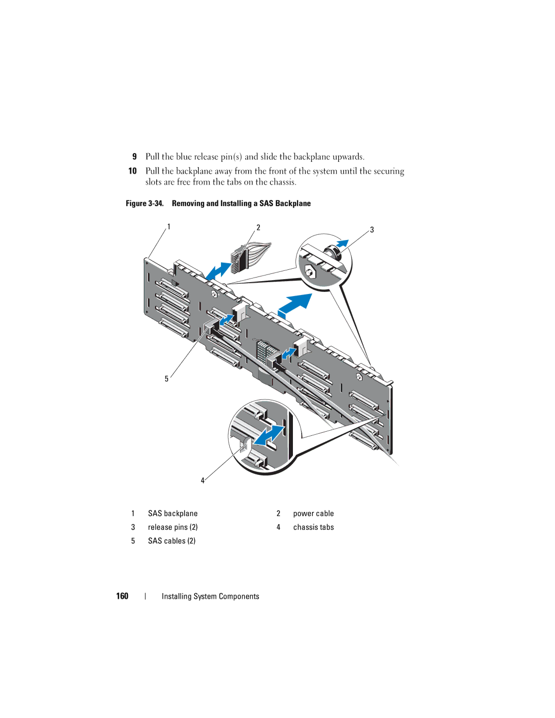
SAS Backplane
Removing the SAS Backplane
160
Installing the SAS Backplane
Power Distribution Board
Removing the Power Distribution Board
35. Power Distribution Board
Tabs Securing slots
Replacing the Power Distribution Board
Control Panel Assembly
Removing the Control Panel Display Module
Installing the Control Panel Display Module
Display module Installing System Components
Control panel board USB cable Control panel cable
Removing the Control Panel Board
Installing the Control Panel Board
System Board
Removing the System Board
Thumbscrew Installing System Components
Installing the System Board
Unpack the new system board
171
172
Troubleshooting External Connections
Troubleshooting Your System
Troubleshooting the Video Subsystem
Troubleshooting a USB Device
Troubleshooting a Serial I/O Device
Troubleshooting a NIC
Troubleshooting a Wet System
Troubleshooting a Damaged System
Troubleshooting the System Battery
Troubleshooting Power Supplies
Troubleshooting System Cooling Problems
Troubleshooting a Fan
Troubleshooting System Memory
Troubleshooting Your System
Troubleshooting an Internal USB Key
Troubleshooting an Internal SD Card
Troubleshooting an Optical Drive
Troubleshooting a Tape Backup Unit
Troubleshooting a Hard Drive
Troubleshooting a Storage Controller
Troubleshooting Your System
Troubleshooting Expansion Cards
Troubleshooting the Processors
191
192
Embedded System Diagnostics Features
Using Online Diagnostics
Running the System Diagnostics
Running the Embedded System Diagnostics
When to Use the Embedded System Diagnostics
System Diagnostics Testing Options
Selecting Devices for Testing
Using the Custom Test Options
Selecting Diagnostics Options
Viewing Information and Results
System Board Jumper Settings Description
Default The password feature is enabled pins
Boot pins
System Board Jumper
System Board Connectors
System Board Connectors
System Board Jumpers and Connectors Description
Control panel interface connector
Control panel USB interface connector
Sata a connector
SAS Backplane Board Connectors
Disabling a Forgotten Password
Hard-drive connectors
Hard-drive connectors Power connector SAS connectors
SAS connector
Jumpers and Connectors
Contacting Dell
Getting Help
204
Using Dell PowerEdge Diagnostics
Index
206
Post
Power supply, 156 system battery
System Utilities screen, 78 Uefi Boot Settings screen
Serial communications options
210