Page
„ Important precautions
Using This Manual „ Contents of this manual
„ Who should use this manual
Warranty
Please Read Prior to Installation for Safety
Installation
Maintenance and Inspection
Wiring
Main Circuit Wiring
Main Circuit Terminal Wiring
PrefaceASDA-AB Series
Table of Contents
Display and Operation
Relationship between Tuning Modes and Parameters
Control Modes of Operation
Chapter
Chapter Troubleshooting 10-1
About this Manual… User Information
Technical Support and Service
This page intentionally left blank
„ Ensure that the product is what you have ordered
Unpacking Check
„ Ensure that the servo motor shaft rotates freely
„ Check for damage
ASDA-AB Series Servo Drive
Model Explanation Nameplate Information
Asmt Series Servo Motor
Model Name Explanation
Ecma Series Servo Motor
Servo Drive and Servo Motor Combinations
Power Servo Drive Servo Motor
220V models
Servo Drive Features
110V models
Control Modes of Servo Drive
Storage Conditions
Installation Notes
Operating Temperature
Installation Conditions
Installation Procedure
Installation Procedure and Minimum Clearances
Drive Mounting
Motor Mounting
„ Minimum Clearances „ Side by Side Installation
220V Servo Drive
Connections Connecting to Peripheral Devices
Connections and WiringASDA-AB Series
CN1
Servo Drive Connectors and Terminals
CN2
CN3
Wiring Notes
Single-Phase Power Supply 1.5kW and below, 220V models
Wiring Methods
Single-Phase Power Supply 400W and below, 110V models
Motor Power Cable Connector Specifications
Case Ground BRAKE1 BRAKE2
Encoder Connector Specifications
Power Cable
Cable Specifications for Servo Drive
GND Braid
Sheld
Encoder Cable
Basic Wiring Schematic of 100W ~ 1.5kW, 220V models
Basic Wiring
Basic Wiring Schematic of 2kW, 220V models
Basic Wiring Schematic of 100W ~ 400W, 110V models
1 CN1 Terminal Identification
Input / Output Interface Connector -CN1
VCC
CN1 Terminal Signal Identification
General Signals Pin No Details Wiring Diagram Refer to
Signals Explanation of Connector CN1
Srdy ALL
Do Signals
SON
Zspd ALL
Tpos
Tspd ALL
TQL
Alrm ALL
DI Signals
TCM1
TCM0
Emgs ALL
CWL
Jogd
Jogu
Stepu
Stepd
Source of Speed Command
Source of Position Command
Source of Torque Command
Default DI signals and Control modes
Reference Home Sensor Reverse operation
Default do signals and Control modes
Wiring Diagrams of I/O Signals CN1
User-defined DI and do signals
User-defined DI and do signals
Connections and WiringASDA-AB Series
Connections and WiringASDA-AB Series
Connections and WiringASDA-AB Series
Connections and WiringASDA-AB Series
CN2 Terminal Signal Identification
Encoder Connector CN2
PIN No Signal Name Terminal Identification Grounding
Connection between PC and Connector CN3
Connections and WiringASDA-AB Series
Position Pt Control Mode 110V models
Position Pr Control Mode 220V models
Position Pr Control Mode 110V models
Speed Control Mode 220V models
Speed Control Mode 110V models
Torque Control Mode 220V models
Torque Control Mode 110V models
This page intentionally left blank
Description of the Digital Keypad
Display and Operation
Keypad Operation
Display Flowchart
Abort Setting Display
Status Display Save Setting Display
Fault Message Display
Polarity Setting Display
Monitor Setting Display
Display and OperationASDA-AB Series
General Function Operation Fault Code Display Operation
JOG Operation
Position Learning Operation
Do Force Output Diagnosis Operation
Do Diagnosis Operation
DI Diagnosis Operation
Inspection without Load
Trial Run and Tuning Procedure
Trial Run and Tuning ProcedureASDA-AB Series
Applying Power to the Drive
Over voltage
Encoder error
Emergency stop activated
Forward limit switch error
Reverse limit switch error
Undervoltage
Overcurrent
JOG Trial Run without Load
Trial Run and Tuning ProcedureASDA-AB Series
Step
Speed Trial Run without Load
DI1
DI8
CCW
Position Trial Run without Load
POS2 POS1 POS0 Ctrg
CCW
Tuning Procedure Display
Tuning Procedure
Tuning Flowchart
Load Inertia Estimation Flowchart
AutoMode PI Tuning Flowchart
Trial Run and Tuning ProcedureASDA-AB Series
Trial Run and Tuning ProcedureASDA-AB Series
Trial Run and Tuning ProcedureASDA-AB Series
Position Mode
Manual Mode Tuning Flowchart
Limit of Load Inertia Estimation
Speed Mode
Gain Adjustment in Manual Mode
Relationship between Tuning Modes and Parameters
KVP
Trial Run and Tuning ProcedureASDA-AB Series
This page intentionally left blank
Control Modes of Operation
Control Modes of Operation
Command Source of Position Pt Control Mode
Position Control Mode
PTT
External Pulse Input Type Communication Addr H
Control Modes of Operation ASDA-AB Series
Command Source of Position Pr Control Mode
Structure of Position Control Mode
Pulse Inhibit Input Function Inhp
Curve Filter for Position Control
Inhp OFF
Acceleration Time Communication Addr H
Tacc
Deceleration Time Communication Addr H
Tdec
TSL
Accel /Decel S-curve Communication Addr H
GR1
Electronic Gear Ratio
GR2
Electronic Gear Ratio Denominator Communication Addr DH
Pflt
Low-pass Filter
PF LT
Position Loop Gain Adjustment
Timing Chart of Position Pr Control Mode
POS0 OFF POS1 POS2 Ctrg SON
Proportional Position Loop Gain Communication Addr H
KPP
PFG
Position Feed Forward Gain Communication Addr H
Control Modes of OperationASDA-AB Series
Command Source of Speed Control Mode
Speed Control Mode
REF-GND
Structure of Speed Control Mode
Curve Filter
Smoothing Strategy of Speed Control Mode
Tacctdec
Analog Speed Command Low-pass Filter
Analog Speed Command S-curve Filter
Sflt
Analog Speed Input Scaling
Max. Analog Speed Command / Limit Communication Addr H
VCM
Speed Loop Gain Adjustment
Timing Chart of Speed Control Mode
SPD0 OFF
SPD1 OFF SON
Manual Mode
Tuning Mode Selection Communication Addr H
AUT2
KVI
KVP
KVF
Frequency Domain
Time Domain
Resonance Suppression
Auto Mode Continuous adjustment
NCF
Notch Filter Resonance Suppression Communication Addr H
NLP
DPH
PWM
Notch Filter
Low-pass filter
Use Notch Filter to suppress resonance
Use Low-pass Filter to suppress resonance
Command Source of Torque Control Mode
Torque Control Mode
Smoothing Strategy of Torque Control Mode
Structure of Torque Control Mode
Tflt
Analog Torque Input Scaling
Max. Analog Torque Command / Limit Communication Addr H
TCM
TCM0 OFF
Timing Chart of Torque Control Mode
TCM1 OFF SON
Pt-S Mode / Pr-S Mode
Speed / Position Control Mode Selection
Control Modes Selection
Ctrg POS0-2 not Care POS0-2 Valid
Torque / Position Control Mode Selection
Speed / Torque Control Mode Selection
Pt-T Mode / Pr-T Mode
Mode
Control Modes of OperationASDA-AB Series
Torque Limit
Others Speed Limit
„ Built-in Regenerative Resistor
Regenerative Resistor
„ External Regenerative Resistor
„ Regenerative Power Calculation Method Without Load
With Load
„ Simple Calculation Method
MON
Analog Monitor
Analog Monitor Output Communication Addr H
Aout
Pulse Output Polarity Setting Communication Addr H
Analog Monitor Output Proportion 1 CH1 Communication Addr H
Analog Monitor Output Proportion 2 CH2 Communication Addr H
DOF2
SON OFF
Electromagnetic Brake
Brkr OFF
Control Modes of OperationASDA-AB Series
Ready Servo on
Ready Servo
This page intentionally left blank
Definition
Explanation of symbols marked after parameter
Abbreviation of control modes
Parameters Summary Parameters List by Group
Default
Group 0 P0-xx
Parameter Name Function
Group 1 P1-xx
Control Parameter Name Function Default Unit Mode
Control
Parameter Name Function Default Unit Mode
Group 2 P2-xx
AUT2
AUT1
INF
Sdev
Group 3 P3-xx
Group 4 P4-xx
Monitor and General Use
Parameters List by Function
Smooth Filter and Resonance Suppression
Gain and Switch
Internal pulse control command Pr mode
External pulse control command Pt mode
PO1H
Combination Output Signal Delay 4ms 12.6 Time P2-46
Speed Control
Torque Control
Digital I/O
Communication
Control
Others
VER
Detailed Parameter Listings
ALE
STS
Status Monitor Communication Addr H
CM1
CM3
CM2
CM4
CM5
MAP1
MAP0
MAP2
MAP3
MAP5
MAP4
MAP6
MAP7
Servo Output Status Display Communication Addr H
Svsts
Group 1 P1-xx Basic Parameters
CTL
Control Mode and Output Direction Communication Addr H
Pstl
Tref Torque Limit P1-121 Command P1-132 P1-143 TCM0 TCM1
MON2
MON1
SP1
Tflt
SP2
TQ1
SP3
TQ3
TQ2
PO1H
PO2H
PO1L
PO2L
PO3H
PO4H
PO3L
PO4L
PO5H
PO6H
PO5L
PO6L
PO7H
PO8H
PO7L
PO8L
MSE
Lstp
Position Control Mode Pr Communication Addr H
Poss
Tacc
GDR
Sspd
Zspd
Max. Analog Torque Command or Limit Communication Addr H
Max. Analog Speed Command or Limit Communication Addr H
MBT1
MBT2
GR2
GR3
Hmov
Homing Mode Communication Addr FH
HSPD2
HSPD1
HOF1
HOF2
RES2
RES1
PER
Mspd
OVW
Cokt
KPP
Position Loop Gain Switching Rate Communication Addr H
PPR
PFF
Speed Loop Gain Switching Rate Communication Addr H
SPR
SFG
KVI
DRT
Pctl
Bounce Filter Communication Addr H
DI2
DI1
Digital Input Terminal 2 DI2 Communication Addr BH
DI3
DI5
DI4
DI6
DI7
DO2
DO1
Digital Output Terminal 2 DO2 Communication Addr H
DO3
Digital Output Terminal 4 DO4 Communication Addr H
DO4
DO5
Digital Output Terminal 5 DO5 Communication Addr H
DST
NLP
GCC
GPE
GUT
INH
AUT1
Auto Mode Responsiveness Level Communication Addr FH
AUT2
Sdev
INF
Pdev
POV2
POV1
POV3
POV4
POV6
POV5
POV7
POV8
DOD
DOM
FSN
PED
Position Deviation Clear Delay Time Communication Addr FH
Blas
Sjit
Dclr
ATM0
Sron
ATM1
ATM2
ATM5
ATM4
ATM6
ATM7
GR6
GR5
Tsca
Tlmod
Torque Limit Mixed Mode Communication Addr H
Bit1 DI TCM0/TCM1 torque command trigger mode
Bit0 DI SPD0/SPD1 speed command trigger mode
Gbit
Bit2 Fast DI contact type
Bit5 Reserved. Must be set to
Bit6 Abnormal pulse command detection
Bit7 ~ Bit9 Reserved. Must be set to
Bit10 DI Zclamp function selection
BRT
ADR
Transmission Speed Communication Addr H
PTL
Transmission Fault Treatment Communication Addr H
Communication Protocol Communication Addr H
FLT
Communication Time Out Detection Communication Addr H
CWD
CMM
Communication Selection Communication Addr H
Digital Input Communication Function Communication Addr H
SDI
CDT
ASH2
ASH1
ASH3
ASH4
JOG Operation Communication Addr H
JOG
Itst
FOT
Input Status or Force Input Control Communication Addr H
Pkey
Output Status Display Communication Addr H
MOT
CEN
SOF1
TOF1
SOF2
TOF2
COF1
COF3
COF2
COF4
Tigb
TAO
SAO
Analog Torque Input Offset Communication Addr H
Reserved Communication Addr H
Input Function Definition
SPD0 SPD1
POS2 OFF
SPD1 OFF
TCM0 TCM1
MD1 MD0
STF STB
STF
Brkr Home
Output Function Definition
Cmdok
Communication Hardware Interface
RS-232 „ Configuration „ Cable Connection
Modbus CommunicationsASDA-AB Series
RS-485, RS-422 „ Configuration
Modbus CommunicationsASDA-AB Series
Modbus CommunicationsASDA-AB Series
Communication Parameter Settings
Modbus CommunicationsASDA-AB Series
DI8 DI7 DI6 DI5 DI4 DI3 DI2 DI1
Modbus CommunicationsASDA-AB Series
RTU Mode
„ Code Description Ascii Mode
Modbus Communication Protocol
„ Data Format
STX
„ Communication Protocol Ascii Mode
CMD
DATA0 LRC
Ascii Mode Command message Response message
CMD Command Codes and Data Data Characters
STX Communication Start
ADR Communication Address
Ascii Mode Command message
RTU Mode Command message Response message
ADR CMD
LRC Ascii Mode
End1, End0 Communication End Ascii Mode
CRC RTU Mode
Modbus CommunicationsASDA-AB Series
Modbus CommunicationsASDA-AB Series
Communication Parameter Write-in and Read-out
Modbus CommunicationsASDA-AB Series
Basic Inspection
Maintenance and Inspection
Life of Replacement Components
Maintenance
„ Smooth capacitor
„ Relay
„ Cooling fan
This page intentionally left blank
Fault Messages Table
Troubleshooting
Display Fault Name Fault Description
Fault Messages
Potential Cause and Corrective Actions
Servo Drive Fault Messages Overcurrent
Overvoltage
Pulse shift
Abnormal pulse control command
Regeneration error
Overload
Overspeed
Adjustment error
Encoder error Position detector fault
Reverse CWL limit switch error
Forward Ccwl limit switch error
Memory error
Igbt temperature error
DSP communication error
Serial communication error
Input power phase loss
Command write-in error
Internal command execution time out
Pre-overload warning
Display Fault Name Clearing Method
Clearing Faults
10-9
This page intentionally left blank 10-10
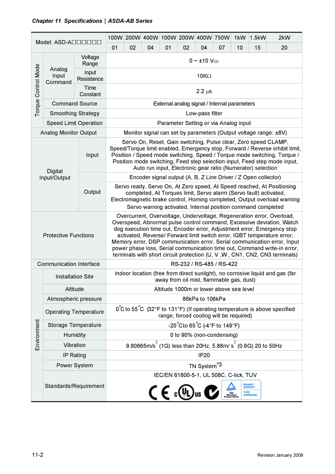
11.1 Specifications of Servo Drive ASDA-AB Series
Specifications
SpecificationsASDA-AB Series
11-3
Low Inertia Servo Motor
Specifications of Servo Motor Ecma Series
Medium / High Inertia Servo Motor
1kW 5kW 2kW
Servo Motor Speed-Torque Curves
„ Chart of load and operating time ECMA-C30401
Overload Characteristics
„ Overload Protection Function
„ Occasion of Overload
„ Chart of load and operating time ECMA-C30604
„ Chart of load and operating time ECMA-C30602
„ Chart of load and operating time ECMA-C30807
„ Chart of load and operating time ECMA-C30804
„ Chart of load and operating time ECMA-C31020
„ Chart of load and operating time ECMA-C31010
„ Chart of load and operating time ECMA-E31305
„ Chart of load and operating time ECMA-G31303
„ Chart of load and operating time ECMA-G31309
„ Chart of load and operating time ECMA-G31306
„ Chart of load and operating time ECMA-E31315
„ Chart of load and operating time ECMA-E31310
„ Chart of load and operating time ECMA-E31820
„ Chart of load and operating time ECMA-E31320
Weight
Dimensions of Servo Drive
11-17
SpecificationsASDA-AB Series
Order P/N ASD-A2023-AB 2kW
Motor Frame Size 80mm and below Models
Dimensions of Servo Motor
Motor Frame Size 100mm and above Models
SpecificationsASDA-AB Series
Position Control including homing function
Parameters Setting
DO1 SR DY DO4 OME DO2 DI1 SON
Roller Feeding
Connecting to Delta DVP-EH Series PLC
TOP
ZE RO
ZRN CL EAR
JOG- F WD P OS ERO OG+ REV POS
JOG+ RST SET
Revpos
RST SET
JOG+
Drva
Drvi JOG
FWD P OS
RET Dmov
RE Vpos
END
Connecting to Delta TP04 Series
12-10
„ Relevant Parameters Description
Position Control Mode Pr Mode
DI=TRIG DI=H OLD
Hold Timing Chart
DI=T RI G DI=CCLR
Command Abort Timing Chart
Feed Step Control
„ Relevant Parameters Description,
„ Digital I/O Signal Setting
MDP0, MDP1
„ Mode Functions
INDEX4 INDEX3 INDEX2 INDEX1 INDEX0 Index Number
„ Definitions of INDEX0~4 ON=1, OFF=0
„ Definitions of do Signals ON=1, OFF=0
„ Timing charts of DI/DO Signals Operation Homing Mode
Index 6 0A
Feed Step Control Mode
Manually Single Step Control Mode
OFF Do Value Index INDEX4
Manually Continuous Step Control Mode
H0FF
„ Communication Control Example Explanation
Homing
Home Sensor on
Internal Auto Running Mode
INDEX6
INDEX5
INDEX7
INDEX8
Alarm
„ Definitions of do Signals ON1, OFF0
DO5 DO4 DO3 DO2 DO1
Manual Control Mode
Auto Running Mode
Do Value CI IDX1 CI IDX2 INDEX4
Manual Control Mode Power on Supply OFF
Motor Speed Servo on
Autor OFF Stepb OFF
Homing Function
Homing Moving Method
Homing Enable Setting
„ Homing Timing Charts Timing Charts of Enable Homing Mode
Homing Stop Setting
„ Recommended Homing Modes
Homing Timing Charts
Power Servo Ready Home Trigger
Homing Completed
A = 0/1 or B/A = 0/3
A = 2/2
A = 2/5
External Controller Connection Examples
„ Connecting to Delta DVP-EH PLC
„ Connecting to Delta DVP-01PU
„ Connecting to Mitsubishi FX1PG
„ Connecting to Mitsubishi FX2N1PG
„ Connecting to Mitsubishi AD75
This page intentionally left blank 12-42
Jowle
„ Power Connectors Delta Part Number ASDBCAPW0000
Delta Part Number ASDBCAPW0100
Delta Part Number ASD-ABPW0103, ASD-ABPW0105
„ Power Cables Delta Part Number ASD-ABPW0003, ASD-ABPW0005
Delta Part Number ASD-CAPW1103, ASD-CAPW1105
„ Power Cables, Delta Part Number ASD-CAPW1003, ASD-CAPW1005
Delta Part Number ASD-CAPW1303, ASD-CAPW1305
„ Power Cables, Delta Part Number ASD-CAPW1203, ASD-CAPW1205
Delta Part Number ASD-CAPW2303, ASD-CAPW2305
„ Power Cables, Delta Part Number ASD-CAPW2203, ASD-CAPW2205
Delta Part Number ASD-CAEN1000
„ Encoder Connectors Delta Part Number ASD-ABEN0000
Delta Part Number ASD-CAEN1003, ASD-CAEN1005
ASD-CAEN1005
„ Terminal Block Module Delta Part Number ASD-BM-50A
„ I/O Signal Connector CN1 Delta Part Number ASD-CNSC0050
ASD-ABEN0003 ASD-ABEN0005
ASD-ABPW0003 ASD-ABPW0005
200W Servo Drive and 200W Low Inertia Servo Motor
ASD-ABPW0003 ASD-ABPW0005 ASD-ABPW0103 ASD-ABPW0105
ASD-CAPW1003 ASD-CAPW1005 ASD-CAPW1103 ASD-CAPW1105
400W Servo Drive and 500W Medium Inertia Servo Motor
ASD-CAEN1003 ASD-CAEN1005
400W Servo Drive and 300W High Inertia Servo Motor
1kW Servo Drive and 1kW Low Inertia Servo Motor
750W Servo Drive and 600W High Inertia Servo Motor
1kW Servo Drive and 1kW Medium Inertia Servo Motor
5kW Servo Drive and 1.5kW Medium Inertia Servo Motor
1kW Servo Drive and 900W High Inertia Servo Motor
2kW Servo Drive and 2kW Low Inertia Servo Motor
ASD-CAPW1203 ASD-CAPW1205 ASD-CAPW1303 ASD-CAPW1305
2kW Servo Drive and 2kW Medium Inertia Servo Motor
Other Accessories
This page intentionally left blank
08TDT1W4S
„ AC Servo Drive EMI Filter Cross Reference
20TDT1W4D
Choose Suitable Motor Cable and Precautions
General Precaution
Saddle on both ends Saddle on one end
Dimensions