DFX-8500
3.2.5 Interlock Switch and Cover Open Sensor Assembly Removal
Step 1: Remove the upper case. (Refer to Section 3.2.3.4)
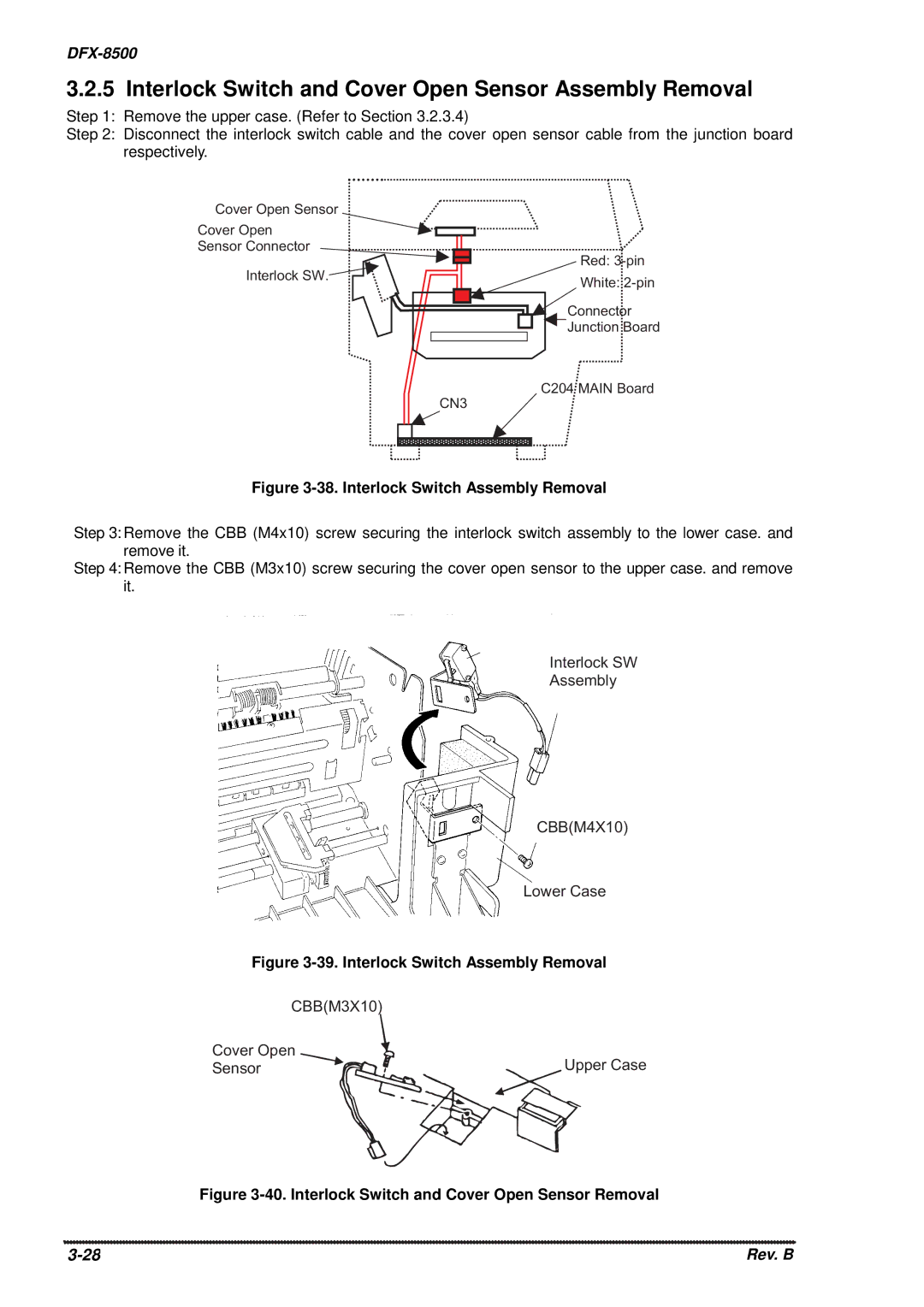
Step 2: Disconnect the interlock switch cable and the cover open sensor cable from the junction board respectively.
C o v e r O p e n S e n s o r
C o v e r | O p e n |
S e n s o r C o n n e c t o r | |
I n t e r lo c k S W . | |
R e d : 3 - p in
W h it e : 2 - p in
C o n n e c t o r
![]()
![]() J u n c t io n B o a r d
J u n c t io n B o a r d
C 2 0 4 M A I N B o a r d
C N 3
Figure 3-38. Interlock Switch Assembly Removal
Step 3: Remove the CBB (M4x10) screw securing the interlock switch assembly to the lower case. and remove it.
Step 4: Remove the CBB (M3x10) screw securing the cover open sensor to the upper case. and remove it.
I n t e r lo c k S W
A s s e m b ly
C B B ( M 4 X 1 0 )
L o w e r C a s e
Figure 3-39. Interlock Switch Assembly Removal
C B B ( M 3 X 1 0 )
C o v e r | O p e n |
S e n s o r | U p p e r C a s e |
Figure 3-40. Interlock Switch and Cover Open Sensor Removal
Rev. B |