DFX-8500
3.2.6.2 Ribbon Feed Change Lever Unit Removal
Step 1: Release the three hooks securing the ribbon feed gear cover to the ribbon feed motor frame and remove the cover and the ribbon feed gear.
Step 2: Disconnect the three connectors for the ribbon feed motor, tractor select sensor, and the ribbon jam sensor from the connector junction board, as shown in Figure
Step 3: Remove the head damper from the left side frame.
Step 4: Remove the fan on the left frame. (Refer to Section 3.2.6.1.)
R ib b o n F e e d G e a r C o v e r
Rib b o n G e a r
H e a d D u m p e r ( L e f t )
F e e d
R ib b o n F e e d | |
C h a n g e | R ib b o n |
L e v e r | |
| M o t o r |
R ib b o n
M o t o r
F e e d U n it
F e e d F r a m e
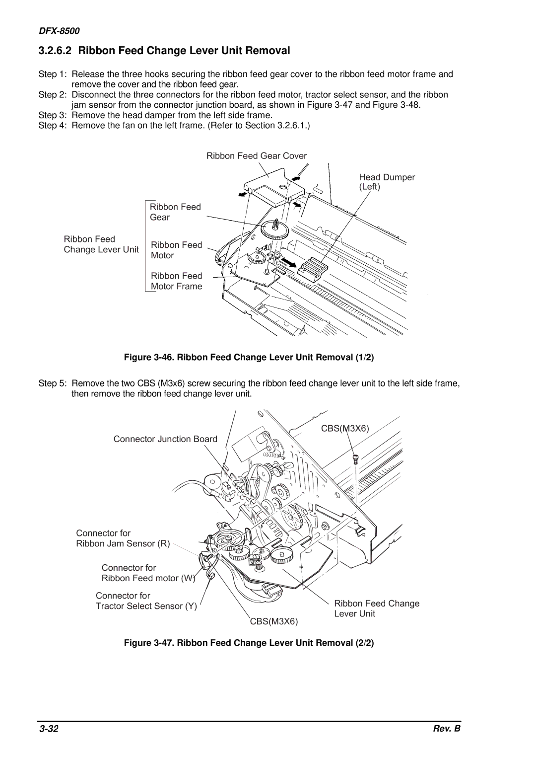
Figure 3-46. Ribbon Feed Change Lever Unit Removal (1/2)
Step 5: Remove the two CBS (M3x6) screw securing the ribbon feed change lever unit to the left side frame, then remove the ribbon feed change lever unit.
C B S ( M 3 X 6 )
C o n n e c t o r J u n c t io n B o a r d
C o n n e c t o r f o r ![]()
R ib b o n J a m![]()
![]()
![]()
![]() S
S ![]() e n s
e n s![]() o
o![]() r ( R )
r ( R )
C o n n e c t o r f o r |
R ib b o n F e e d m o t o r ( W ) |
C o n n e c t o r f o r
T r a c t o r S e le c t S e n s o r ( Y )
R ib b o n F e e d C h a
L e v e r U n it
C B S ( M 3 X 6 )
Figure 3-47. Ribbon Feed Change Lever Unit Removal (2/2)
Rev. B |