DISASSEMBLY AND ASSEMBLY
3.2.6.17 Front Tractor Assembly Removal
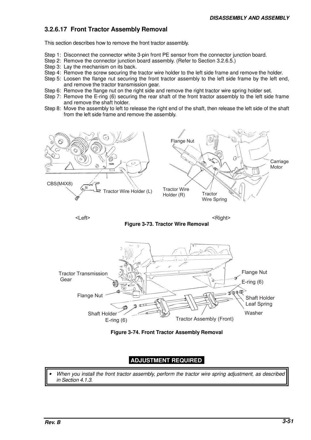
This section describes how to remove the front tractor assembly.
Step 1: Disconnect the connector white
Step 2: Remove the connector junction board assembly. (Refer to Section 3.2.6.5.)
Step 3: Lay the mechanism on its back.
Step 4: Remove the screw securing the tractor wire holder to the left side frame and remove the holder.
Step 5: Loosen the flange nut securing the front tractor assembly to the left side frame by the left end, and remove the tractor transmission gear.
Step 6: Remove the flange nut on the right side and remove the right tractor wire spring holder set.
Step 7: Remove the
Step 8: Move the assembly to left to release the right end of the shaft, then release the left side of the shaft from the left side frame and remove the assembly.
F la n g e![]()
![]() N u
N u![]() t
t
![]() C a r r ia
C a r r ia
M o t o r
C B S ( M 4![]() X 8 )
X 8 ) ![]()
![]() T r a
T r a
T r a c t o r W ir e c t o r W ir e H o ld e r ( L
H o ld e rT r(aRc)t o r
W ir e S ![]() p r in g
p r in g
< L e f t > | < R i g h t > |
Figure 3-73. Tractor Wire Removal
T r a c t o r T![]()
![]() r a
r a![]()
![]() n s m is s io n
n s m is s io n![]()
G e a r |
|
F la n g e | N u t |
S h a f t | H o ld e r |
E - r in g (![]() 6 )T r a c t o r
6 )T r a c t o r
Figure 3-74. Front Tractor Assembly Removal
F la n g e | N u |
E - r in g | ( 6 ) |
S h a f t | H o l |
L e a f S p r i
W a s h e r
A s s e m b ly (
ADJUSTMENT REQUIRED
∙When you install the front tractor assembly, perform the tractor wire spring adjustment, as described in Section 4.1.3.
Rev. B |