DFX-8500
2.2.1 Power Supply Overview
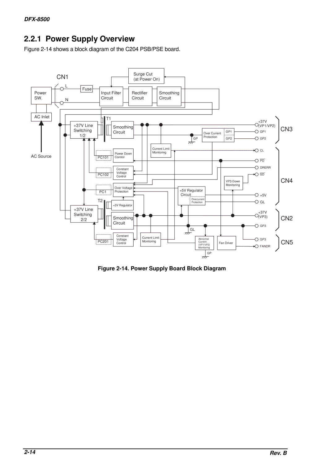
Figure 2-14 shows a block diagram of the C204 PSB/PSE board.
Power
SW.
AC Inlet
AC Source
CN1 |
|
| Surge Cut |
|
|
|
| |
|
| (at Power On) |
|
|
|
| ||
|
|
|
|
|
|
| ||
L | Fuse |
|
|
|
|
|
|
|
|
|
| Smoothing |
|
|
|
| |
| Input Filter | Rectifier |
|
|
|
| ||
N | Circuit |
| Circuit | Circuit |
|
|
|
|
|
|
|
|
|
|
|
| |
| T1 |
|
|
|
|
|
| +37V |
| +37V Line |
|
|
|
|
|
| |
| Smoothing |
|
|
|
| (VP1/VP2) | ||
| Switching |
|
|
|
|
| ||
| Circuit |
|
| Over Current | GP1 | GP1 | ||
| 1/2 |
|
|
|
| |||
|
|
| GP | Protection |
| GP2 | GP2 | |
|
|
|
|
|
| |||
|
|
|
| Current Limit |
|
|
| CL |
|
| Power Down |
| Monitoring |
|
|
| |
|
|
|
|
|
|
| ||
|
|
|
|
|
|
|
| |
| PC101 | Control |
|
|
|
|
| PD |
|
|
|
|
|
|
|
| |
|
| Constant |
|
|
|
|
| DRERR |
|
|
|
|
|
|
|
| |
| PC102 | Voltage |
|
|
|
|
| SD |
| Control |
|
|
|
|
| ||
|
|
|
|
|
|
|
| |
|
|
|
|
|
|
| VP3 Down |
|
|
| Over Voltage |
|
|
| Monitoring |
| |
|
| +5V Regulator |
|
|
| |||
| PC1 | Protection |
|
|
|
| ||
|
| Circuit |
|
|
| +5V | ||
|
|
|
|
|
|
| ||
| T2 |
|
| Overcurrent |
|
| GL | |
|
|
| Protection |
|
| |||
|
| +5V Regulator |
|
| ||||
|
|
|
|
|
|
| ||
| +37V Line |
|
|
|
|
|
| +37V |
| Switching |
|
|
|
|
|
| |
| Smoothing |
|
|
|
| (VP3) | ||
| 2/2 |
|
|
|
| |||
|
|
|
|
|
| |||
| Circuit |
|
|
|
|
|
| |
|
|
|
|
|
|
| GP3 | |
|
|
|
|
|
|
|
| |
|
|
|
| GL |
|
|
|
|
|
| Constant | Current Limit |
|
|
|
| |
|
| Voltage | Abnormal |
|
| GP3 | ||
| PC201 | Monitoring |
|
| ||||
| Control | Current | Fan Driver |
| ||||
|
|
|
| (VP1/VP2) |
| |||
|
|
|
|
|
|
| FANDR | |
|
|
|
|
| Monitoring |
|
| |
|
|
|
|
|
|
|
| |
|
|
|
|
| GP |
|
|
|
CN3
CN4
CN2
CN5
Figure 2-14. Power Supply Board Block Diagram
Rev. B |