DFX-8500
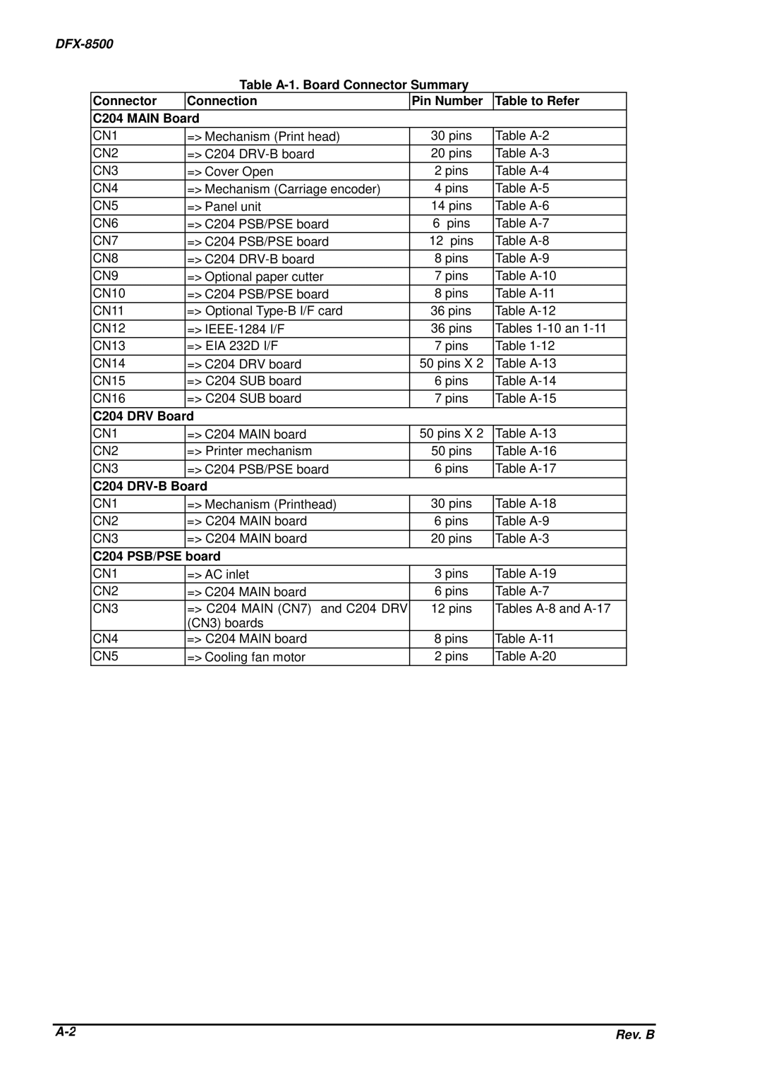
Table
Connector | Connection | Pin Number | Table to Refer |
C204 MAIN Board |
|
| |
|
|
|
|
CN1 | => Mechanism (Print head) | 30 pins | Table |
CN2 | => C204 | 20 pins | Table |
CN3 | => Cover Open | 2 pins | Table |
CN4 | => Mechanism (Carriage encoder) | 4 pins | Table |
CN5 | => Panel unit | 14 pins | Table |
CN6 | => C204 PSB/PSE board | 6 pins | Table |
CN7 | => C204 PSB/PSE board | 12 pins | Table |
CN8 | => C204 | 8 pins | Table |
CN9 | => Optional paper cutter | 7 pins | Table |
CN10 | => C204 PSB/PSE board | 8 pins | Table |
CN11 | => Optional | 36 pins | Table |
|
|
|
|
CN12 | => | 36 pins | Tables |
CN13 | => EIA 232D I/F | 7 pins | Table |
|
|
|
|
CN14 | => C204 DRV board | 50 pins X 2 | Table |
CN15 | => C204 SUB board | 6 pins | Table |
|
|
|
|
CN16 | => C204 SUB board | 7 pins | Table |
|
|
|
|
C204 DRV Board |
|
| |
|
|
|
|
CN1 | => C204 MAIN board | 50 pins X 2 | Table |
CN2 | => Printer mechanism | 50 pins | Table |
|
|
|
|
CN3 | => C204 PSB/PSE board | 6 pins | Table |
C204 |
|
| |
|
|
|
|
CN1 | => Mechanism (Printhead) | 30 pins | Table |
CN2 | => C204 MAIN board | 6 pins | Table |
|
|
|
|
CN3 | => C204 MAIN board | 20 pins | Table |
|
|
|
|
C204 PSB/PSE board |
|
| |
|
|
|
|
CN1 | => AC inlet | 3 pins | Table |
CN2 | => C204 MAIN board | 6 pins | Table |
CN3 | => C204 MAIN (CN7) and C204 DRV | 12 pins | Tables |
| (CN3) boards |
|
|
CN4 | => C204 MAIN board | 8 pins | Table |
|
|
|
|
CN5 | => Cooling fan motor | 2 pins | Table |
Rev. B |
