DFX-8500
2.3.3 Sensor Circuits
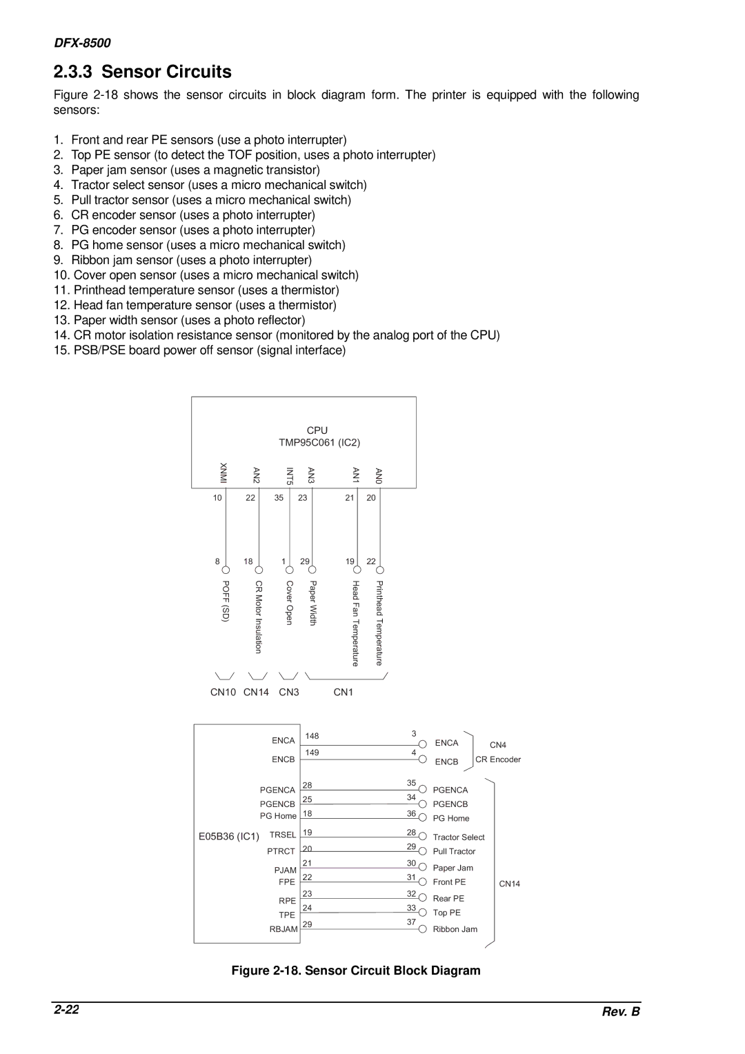
Figure 2-18 shows the sensor circuits in block diagram form. The printer is equipped with the following sensors:
1.Front and rear PE sensors (use a photo interrupter)
2.Top PE sensor (to detect the TOF position, uses a photo interrupter)
3.Paper jam sensor (uses a magnetic transistor)
4.Tractor select sensor (uses a micro mechanical switch)
5.Pull tractor sensor (uses a micro mechanical switch)
6.CR encoder sensor (uses a photo interrupter)
7.PG encoder sensor (uses a photo interrupter)
8.PG home sensor (uses a micro mechanical switch)
9.Ribbon jam sensor (uses a photo interrupter)
10.Cover open sensor (uses a micro mechanical switch)
11.Printhead temperature sensor (uses a thermistor)
12.Head fan temperature sensor (uses a thermistor)
13.Paper width sensor (uses a photo reflector)
14.CR motor isolation resistance sensor (monitored by the analog port of the CPU)
15.PSB/PSE board power off sensor (signal interface)
|
|
| CPU |
|
|
|
| TMP95C061 (IC2) |
| ||
XNMI | AN2 | INT5 | AN3 | AN1 | AN0 |
10 | 22 | 35 | 23 | 21 | 20 |
8 | 18 | 1 | 29 | 19 | 22 |
|
|
|
POFF (SD) | CR Motor Insulation | Cover Open | Paper Width | Head Fan Temperature | Printhead Temperature |
|
|
|
CN10 | CN14 | CN3 |
| CN1 |
|
|
|
|
|
| ENCA | 148 |
| 3 |
|
|
|
|
|
|
| ENCA |
|
| ||
|
|
|
|
|
| CN4 | ||
|
|
| 149 |
| 4 |
| ||
|
| ENCB |
|
| CR Encoder | |||
|
|
|
|
| ENCB | |||
|
|
|
|
|
|
|
| |
| PGENCA | 28 |
| 35 | PGENCA |
|
| |
|
| 34 |
|
| ||||
| PGENCB | 25 |
| PGENCB |
|
| ||
|
|
|
|
| ||||
| PG Home | 18 |
| 36 | PG Home |
|
| |
|
|
|
|
|
|
|
| |
E05B36 (IC1) | TRSEL | 19 |
| 28 | Tractor Select |
| ||
| PTRCT | 20 |
| 29 | Pull Tractor |
|
| |
|
|
|
|
| ||||
|
| PJAM | 21 |
| 30 | Paper Jam |
|
|
|
|
|
|
|
|
| ||
|
| 22 |
| 31 |
|
|
| |
|
| FPE |
| Front PE |
| CN14 | ||
|
| RPE | 23 |
| 32 | Rear PE |
|
|
|
|
|
|
|
|
| ||
|
| 24 |
| 33 |
|
|
| |
|
| TPE |
| Top PE |
|
| ||
|
|
|
|
|
|
| ||
|
|
|
| 37 |
|
|
| |
|
| RBJAM 29 |
| Ribbon Jam |
| |||
|
|
|
|
| ||||
Figure 2-18. Sensor Circuit Block Diagram
Rev. B |