DISASSEMBLY AND ASSEMBLY
3.2.6.14 PG Home Sensor Removal
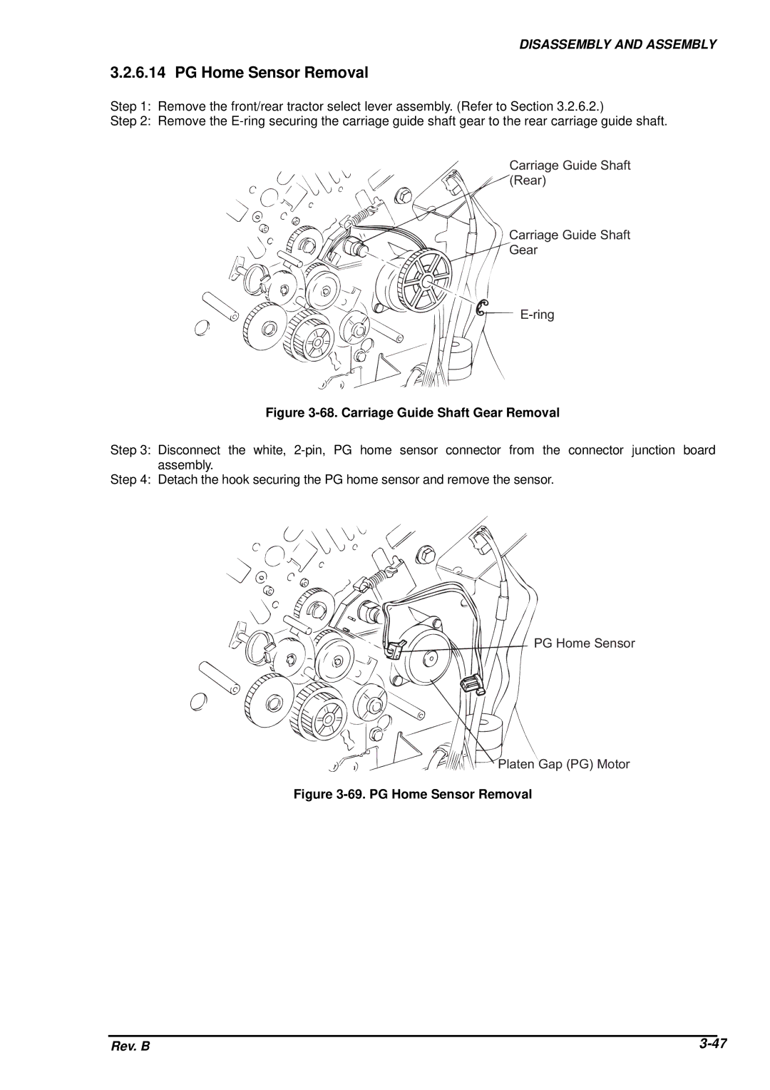
Step 1: Remove the front/rear tractor select lever assembly. (Refer to Section 3.2.6.2.)
Step 2: Remove the
C a r r ia g e G u id e ( R e a r )
C a r r ia g e G u id e
G e a r
E - r in g
Figure 3-68. Carriage Guide Shaft Gear Removal
Step 3: Disconnect the white,
Step 4: Detach the hook securing the PG home sensor and remove the sensor.
P G H o m e S e n s
P la t e n G a p ( P G
Figure 3-69. PG Home Sensor Removal
Rev. B |