OPERATING PRINCIPLES
Table
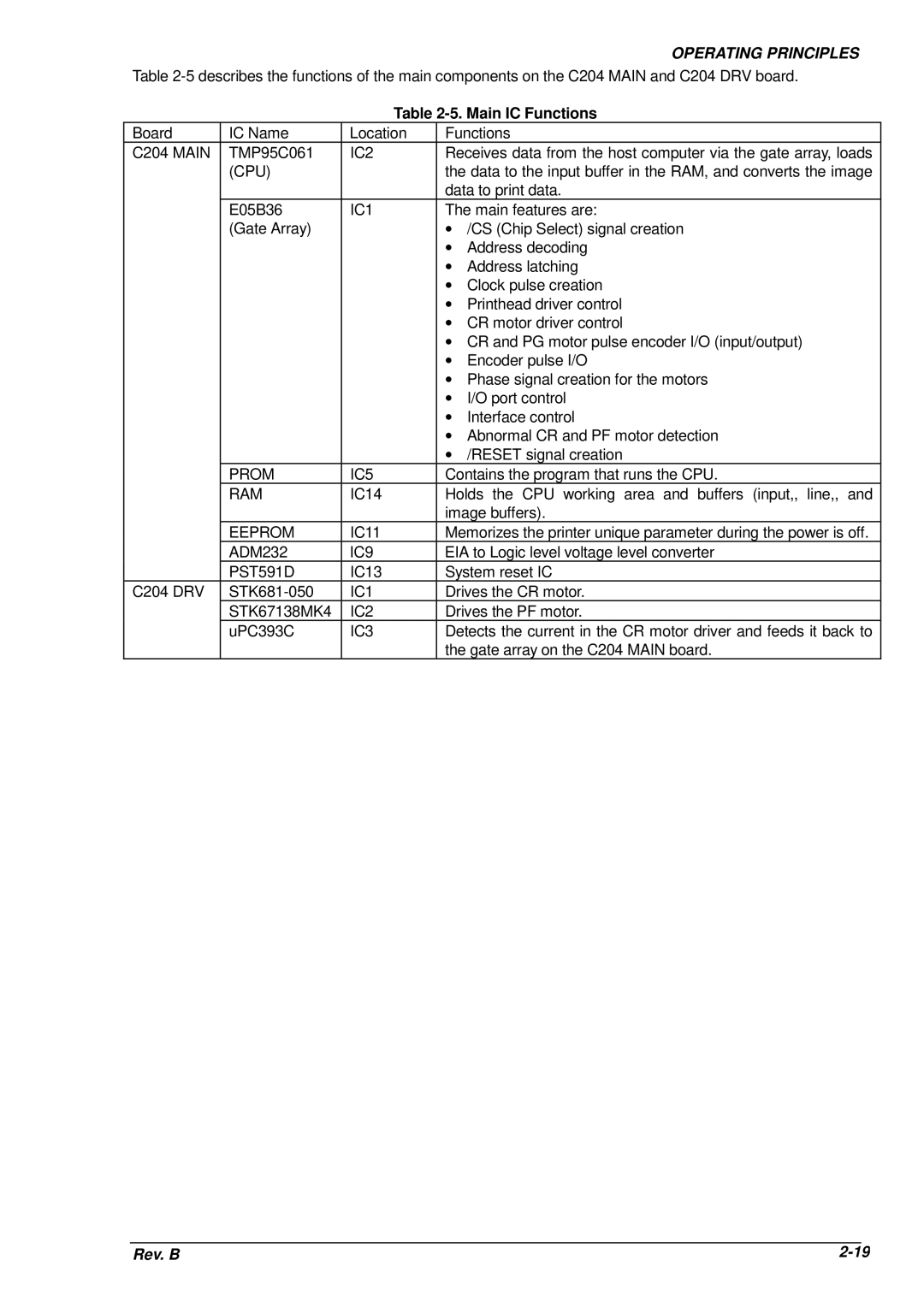
Table 2-5. Main IC Functions
Board | IC Name | Location | Functions | |
C204 MAIN | TMP95C061 | IC2 | Receives data from the host computer via the gate array, loads | |
| (CPU) |
| the data to the input buffer in the RAM, and converts the image | |
|
|
| data to print data. | |
| E05B36 | IC1 | The main features are: | |
| (Gate Array) |
| ∙ /CS (Chip Select) signal creation | |
|
|
| ∙ | Address decoding |
|
|
| ∙ | Address latching |
|
|
| ∙ | Clock pulse creation |
|
|
| ∙ | Printhead driver control |
|
|
| ∙ CR motor driver control | |
|
|
| ∙ CR and PG motor pulse encoder I/O (input/output) | |
|
|
| ∙ | Encoder pulse I/O |
|
|
| ∙ Phase signal creation for the motors | |
|
|
| ∙ | I/O port control |
|
|
| ∙ | Interface control |
|
|
| ∙ Abnormal CR and PF motor detection | |
|
|
| ∙ | /RESET signal creation |
| PROM | IC5 | Contains the program that runs the CPU. | |
| RAM | IC14 | Holds the CPU working area and buffers (input,, line,, and | |
|
|
| image buffers). | |
| EEPROM | IC11 | Memorizes the printer unique parameter during the power is off. | |
| ADM232 | IC9 | EIA to Logic level voltage level converter | |
| PST591D | IC13 | System reset IC | |
C204 DRV | IC1 | Drives the CR motor. | ||
| STK67138MK4 | IC2 | Drives the PF motor. | |
| uPC393C | IC3 | Detects the current in the CR motor driver and feeds it back to | |
|
|
| the gate array on the C204 MAIN board. | |
Rev. B |
