DFX-8500
3.2.6.8 Upper Paper Guide and Top PE Sensor Removal
Step 1: Remove the paper bail assembly. (Refer to Section 3.2.6.7)
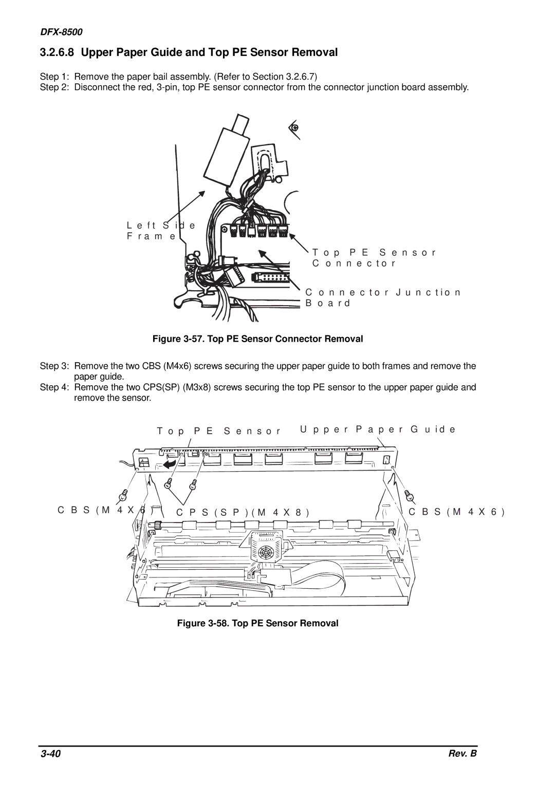
Step 2: Disconnect the red,
L e f t S id e![]()
![]()
![]()
F r a m e
T o p P E S e n s o r
C o n n e c t o r
C o n n e c t o r J u n c t io n
B o a r d
Figure 3-57. Top PE Sensor Connector Removal
Step 3: Remove the two CBS (M4x6) screws securing the upper paper guide to both frames and remove the paper guide.
Step 4: Remove the two CPS(SP) (M3x8) screws securing the top PE sensor to the upper paper guide and remove the sensor.
U p p e r P a p e r G u id e | |
T o p P E S e n s o r |
|
C B S ( M 4 X 6 ) | C B S ( M 4 X 6 ) |
C P S ( S P ) ( M 4 X 8 ) | |
Figure 3-58. Top PE Sensor Removal
Rev. B |