DISASSEMBLY AND ASSEMBLY
3.2.6.15 PF Motor Removal
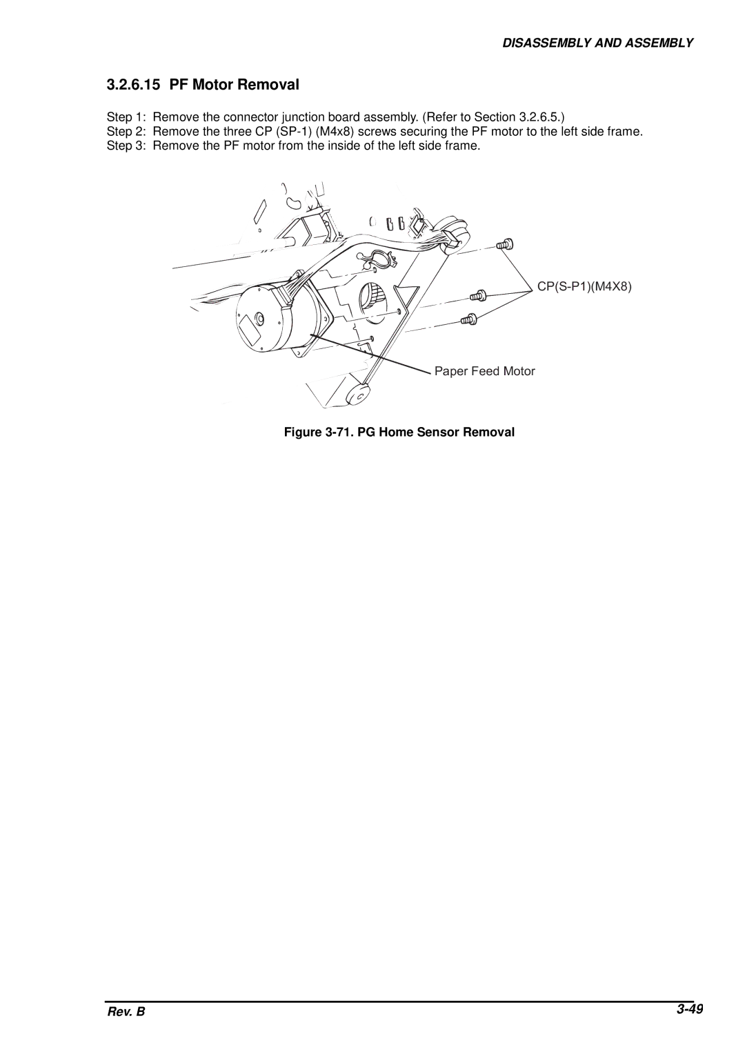
Step 1: Remove the connector junction board assembly. (Refer to Section 3.2.6.5.)
Step 2: Remove the three CP
Step 3: Remove the PF motor from the inside of the left side frame.
C P ( S - P 1 ) ( M 4
P a p e r F e e d M o t o r
Figure 3-71. PG Home Sensor Removal
Rev. B |