DISASSEMBLY AND ASSEMBLY
3.2.6.10 Platen Removal
Step 1: Remove the paper bail assembly. (Refer to Section 3.2.6.7.)
Step 2: Remove the upper paper guide. (Refer to Section 3.2.6.8.)
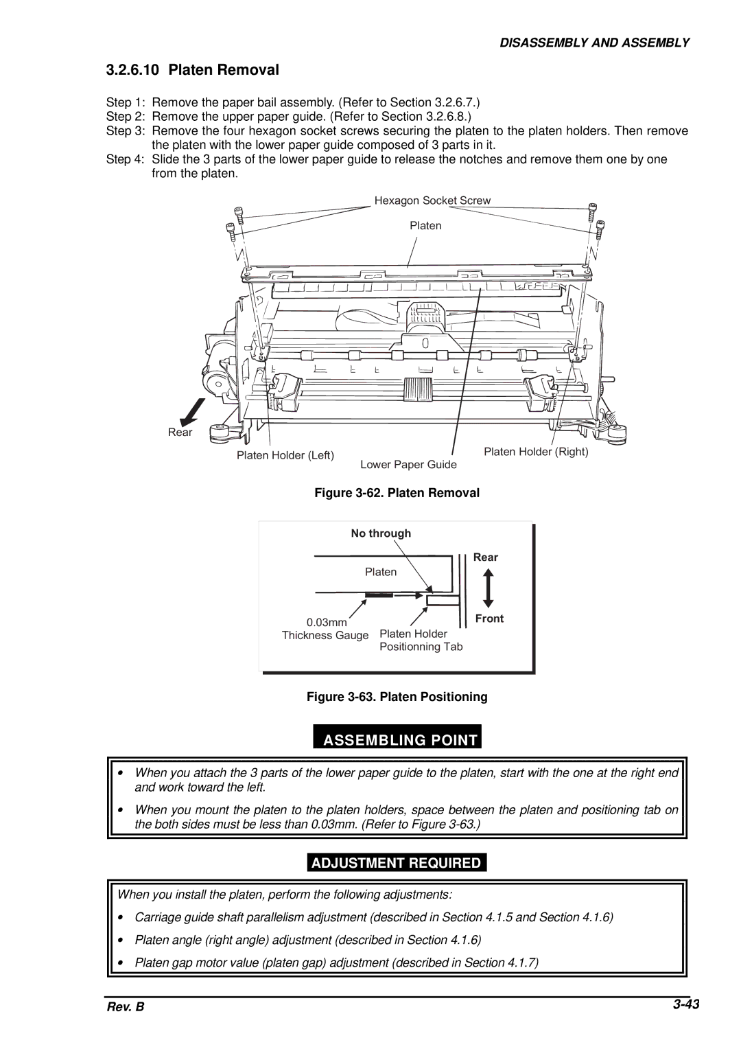
Step 3: Remove the four hexagon socket screws securing the platen to the platen holders. Then remove the platen with the lower paper guide composed of 3 parts in it.
Step 4: Slide the 3 parts of the lower paper guide to release the notches and remove them one by one from the platen.
H e x a g o n S o c k e t S c r e w
P la t e n
R e a![]() r
r
P la t e n H o ld e r ( R
P la t e n H o ld e r ( L e f t )
L o w e r P a p e r G u id e
Figure 3-62. Platen Removal
N o t h r o u g h
R e a r
P l a t e n
0 . 0 3 mFmr o n t
T h ic k n Pe las st eG na uHgoeld e r
P o s it io n n in g T a b
Figure 3-63. Platen Positioning
ASSEMBLING POINT
∙When you attach the 3 parts of the lower paper guide to the platen, start with the one at the right end and work toward the left.
∙When you mount the platen to the platen holders, space between the platen and positioning tab on the both sides must be less than 0.03mm. (Refer to Figure
ADJUSTMENT REQUIRED
When you install the platen, perform the following adjustments:
∙Carriage guide shaft parallelism adjustment (described in Section 4.1.5 and Section 4.1.6)
∙Platen angle (right angle) adjustment (described in Section 4.1.6)
∙Platen gap motor value (platen gap) adjustment (described in Section 4.1.7)
|
|
|
Rev. B | ||
