T r a c | e n s o | n s o r | s o r | o r |
|
| S |
| n | s |
|
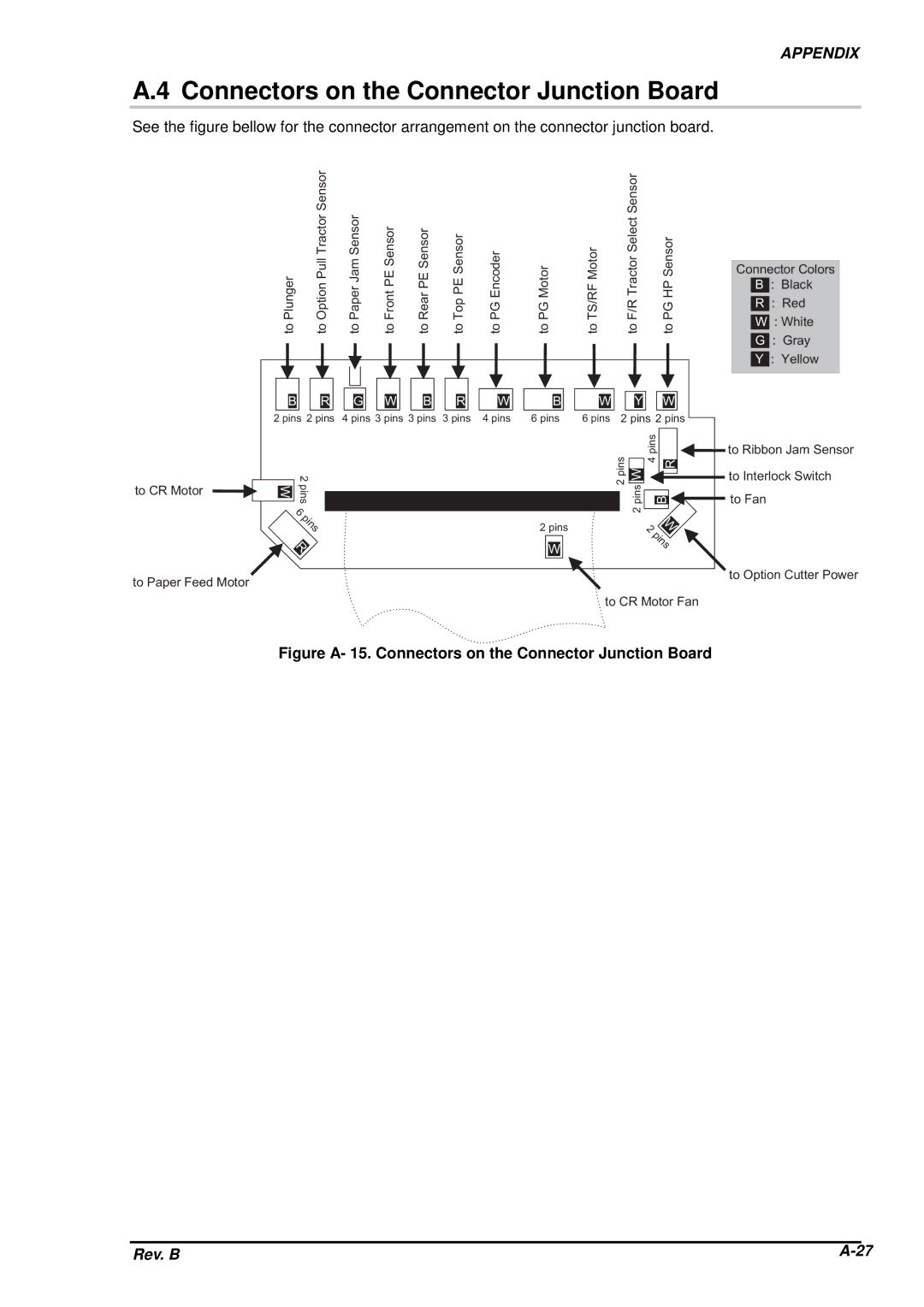
A.4 Connectors on the |
|
| |||
llu | m | S | Connector | ||
S | e | e | |||
|
|
| e | n |
|
See the figure bellow for the connector arrangement on the | ||||||
n g e r | io n P | e r J a | n t P E | r P E | P E S | E n c o d |
lu | p t | a p | r o | e a | o p | G |
P | O | P | F | R | T | P |
|
| S e le | r |
Junctionr r | Boardso | ||
| to | o | n |
connector junction board. | |||
o t o r | F M o | T r a c | P S e |
M | R |
| H |
P G | T S / | F / R | P G |
APPENDIX
C o n n e c t o r | ||||
| B | : | B la c k | |
|
|
| : | R e d |
| R |
| ||
t o | t o | t o | t o | t o | t o | t o | t o | t o | t o | t o |
W : W h it e |
G: G r a y Y : Y e llo
|
|
|
|
|
|
|
|
| s |
|
|
|
|
|
|
|
| B R G W B R W | B W |
| Y | W |
|
|
|
| |||
|
| 2 | p2 inp4sinp3sinp3sinp sin 4s |
|
| s |
| in |
|
| p in s |
| ||
|
| 3p in6pinspins s 2 | 6p inp ins s2 |
| ||||||||||
|
|
|
|
|
|
| in | s p |
|
|
|
|
| |
|
|
|
|
|
|
| 2 p | pWin | 4 | R | t o | R ib b o n | J | |
t o | C R |
| 2 |
|
|
| t o I n t e r lo c | |||||||
M oWt o r |
|
|
|
| B | t o | F a n |
| ||||||
|
|
| 6p |
|
|
|
| 2 |
| |||||
|
|
|
|
|
|
|
|
|
|
| ||||
|
|
| in | p | 2 | p in s |
| 2 | W |
|
|
|
| |
|
|
|
|
|
|
|
|
| ||||||
|
|
|
|
|
|
|
|
|
|
|
|
| ||
|
|
| in |
|
|
|
|
|
|
|
|
|
| |
|
|
| R | W |
|
|
| p |
|
|
|
| ||
|
|
| s |
|
|
|
|
|
|
| ||||
|
|
| s |
|
|
|
|
| in |
|
|
|
| |
|
|
|
|
|
|
|
|
| t o | O p t io n | C | |||
t o P a p e r F e e d M o t o r |
|
|
|
|
| |||||||||
|
|
|
|
| s | |||||||||
|
|
|
|
|
|
|
|
| ||||||
|
|
|
|
|
| t o C R M o t o r F a n |
| |||||||
Figure A- 15. Connectors on the Connector Junction Board
|
|
|
Rev. B | ||