DISASSEMBLY AND ASSEMBLY
Step 5: Disconnect the narrow FPC cable from white connector
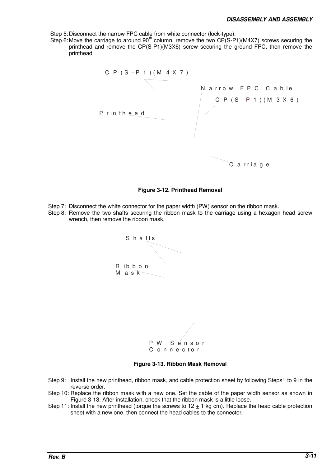
Step 6: Move the carriage to around 90th column, remove the two
C P ( S - P 1 ) ( M 4 X 7 )
N a r r o w F P C C a b le
C P ( S - P 1 ) ( M 3 X 6 )
P r in t h e a d
C a r r ia g e
Figure 3-12. Printhead Removal
Step 7: Disconnect the white connector for the paper width (PW) sensor on the ribbon mask.
Step 8: Remove the two shafts securing the ribbon mask to the carriage using a hexagon head screw wrench, then remove the ribbon mask.
S h a f t s
Rib b o n M a s k
P W S e n s o r
C o n n e c t o r
Figure 3-13. Ribbon Mask Removal
Step 9: Install the new printhead, ribbon mask, and cable protection sheet by following Steps1 to 9 in the reverse order.
Step 10: Replace the ribbon mask with a new one. Set the cable of the paper width sensor as shown in Figure
Step 11: Install the new printhead (torque the screws to 12 + 1 kg cm). Replace the head cable protection sheet with a new one, then connect the head cables to the connector.
Rev. B |