DFX-8500
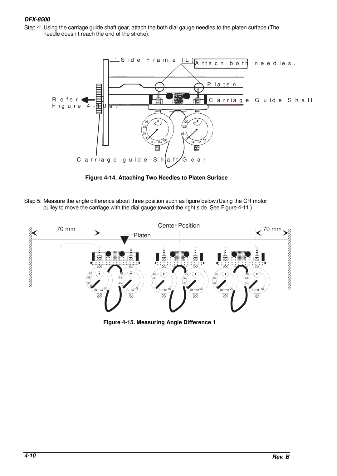
Step 4: Using the carriage guide shaft gear, attach the both dial gauge needles to the platen surface.(The needle doesn’t reach the end of the stroke).
S id e F r a m e ( L )
A t t a c h b o t h
![]() P la t e n
P la t e n
R e f e r t o | C a r r ia g e |
F ig u r e 4 - 1 0 a . |
|
n e e d le
G u id e S
C a r r ia g e g u id e S h a f t G e a r
Figure 4-14. Attaching Two Needles to Platen Surface
Step 5: Measure the angle difference about three position such as figure below.(Using the CR motor pulley to move the carriage with the dial gauge toward the right side. See Figure
70 mm |
|
|
|
|
| Center Position |
|
|
|
|
|
| 70 mm | |||||
|
|
| Platen |
|
|
|
|
|
|
|
|
|
|
| ||||
|
|
|
|
|
|
|
|
|
|
|
|
|
|
|
| |||
30 |
|
| 30 |
|
| 30 |
|
| 30 |
|
| 30 |
|
| 30 |
|
| |
20 |
|
| 20 |
|
| 20 |
|
| 20 |
|
| 20 |
|
| 20 |
|
| |
10 |
|
| 10 |
|
| 10 |
|
| 10 |
|
| 10 |
|
| 10 |
|
| |
0 |
| 30 | 0 |
| 30 | 0 |
| 30 | 0 |
| 30 | 0 |
| 30 | 0 |
| 30 | |
10 | 20 | 10 | 20 | 10 | 20 | 10 | 20 | 10 | 20 | 10 | 20 | |||||||
|
|
|
|
|
| |||||||||||||
Figure 4-15. Measuring Angle Difference 1
Rev. B |
