DFX-8500
1.2.12.4 Overlapping Multi-part Form
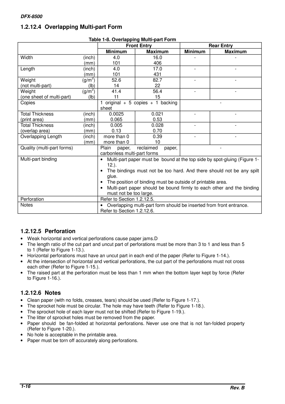
Table
|
| Front Entry |
|
| Rear Entry | ||
|
| Minimum | Maximum | Minimum |
| Maximum | |
Width | (inch) | 4.0 | 16.0 | - |
| - | |
| (mm) | 101 | 406 |
|
|
| |
Length | (inch) | 4.0 | 17.0 | - |
| - | |
| (mm) | 101 | 431 |
|
|
| |
Weight | (g/m2) | 52.6 | 82.7 | - |
| - | |
(not | (lb) | 14 | 22 |
|
|
|
|
Weight | (g/m2) | 41.4 | 56.4 | - |
| - | |
(one sheet of | (lb) | 11 | 15 |
|
|
|
|
Copies |
| 1 original + 5 | copies + 1 | backing |
|
| - |
|
| sheet |
|
|
|
|
|
Total Thickness | (inch) | 0.0025 | 0.021 | - |
| - | |
(print area) | (mm) | 0.065 | 0.53 |
|
|
| |
Total Thickness | (inch) | 0.005 | 0.028 | - |
| - | |
(overlap area) | (mm) | 0.13 | 0.70 |
|
|
| |
Overlapping Length | (inch) | more than 0 | 0.39 | - |
| - | |
| (mm) | more than 0 | 10 |
|
|
|
|
Quality |
| Plain paper, | reclaimed | paper, |
|
| - |
|
| carbonless |
|
|
|
| |
| ∙ | bound at the top side by | |||||
|
| 12.). |
|
|
|
|
|
|
| ∙ The bindings must not be too hard. And there should not be any spilt | |||||
|
| glue. |
|
|
|
|
|
|
| ∙ The position of binding must be outside of printable area. | |||||
|
| ∙ | |||||
|
| must not be too large. |
|
|
|
| |
Perforation |
| Refer to Section 1.2.12.5. |
|
|
|
| |
Notes |
| ∙ Overlapping | |||||
|
| Refer to Section 1.2.12.6. |
|
|
|
| |
1.2.12.5 Perforation
∙Weak horizontal and vertical perforations cause paper jams.D
∙The length ratio of the cut part and uncut part of perforations must be more than 3 to 1 and less than 5 to 1 (Refer to Figure
∙Horizontal perforations must have an uncut part in each end of the paper (Refer to Figure
∙At the intersection of horizontal and vertical perforations, the cut part of the perforations must not cross each other (Refer to Figure
∙The raised part at the perforation must be less than 1 mm when the bottom layer kept by force (Refer to Figure
1.2.12.6 Notes
∙Clean paper (with no folds, creases, tears) should be used (Refer to Figure
∙The sprocket hole must be circular. The hole may have teeth (Refer to Figure
∙The sprocket hole of each layer must not be shifted (Refer to Figure
∙The litter of sprocket holes must be removed from the paper.
∙Paper should be
∙No hole is acceptable in the printable area.
∙Paper must be torn off accurately along perforations.
Rev. B | |
|