Manuals
/
Epson
/
Computer Equipment
/
All in One Printer
Epson
DFX-8500
service manual
Maintenance
Models:
DFX-8500
1
207
245
245
Download
245 pages
33.2 Kb
204
205
206
207
208
209
210
211
Troubleshooting
Specification
Error codes
Circuit Diagrams
‰Control and status signals
Errors and Buzzers
Indicators
Tractor Wire Operation
Maintenance
Reset IC
Page 207
Image 207
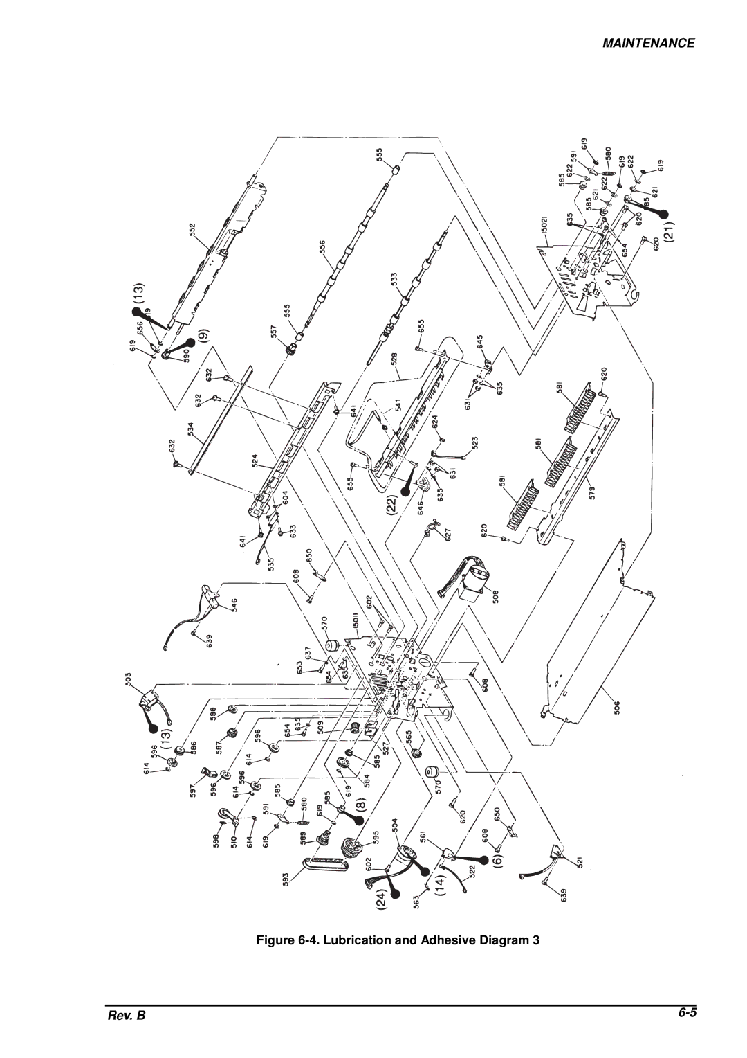
MAINTENANCE
Figure
6-4.
Lubrication and Adhesive Diagram 3
Rev. B
6-5
Page 206
Page 208
Page 207
Image 207
Page 206
Page 208
Contents
DFX-8500
Copyright 1998 by Seiko Epson Corporation Nagano, Japan
Precautions
Preface
Revision Sheet
Revision Issued Data Contents
Table of Contents
Chapter
Page
DFX-8500 Exterior View
Features
Code Name
Option
Specifications
Printing Specification
NLQ
UPC-A UPC-E
Brascii
PC866 UKR PC Aptec
USA
BRASCII*1
Character tables and type faces Character Table Bitmap Font
Reliability
Electrical Specification
Paper Feeding
Environmental Condition
Acoustic Noise
Safety Approvals
Physical Specifications
CE Marking
Continuous Paper
Printable area
MR M
C D Y Z
General Description
Paper and Media
Continuous paper Single sheet and multi-part
Continuous Paper Front Entry Rear Entry Minimum Maximum
Paper-stapling Height
Width Height Inch
Labels
Labels Front Entry Rear Entry Minimum Maximum
Form Labels
Avery Continuous Form Labels
Continuous Forms with Labels
Perforation
Overlapping Multi-part Form
12. Paper Width Overlapping Area
16. Raised Portion at a Perforation
Parallel Interface Forward channel
Interfaces
Signal Level Parameter Minimum Maximum Condition
Parallel Interface Reverse channel
Optional Interface
Serial Interface
Prevention Hosts from Data Transfer Time-out
Interface Selection
Control Panel
Operating Instructions
Switches
Indicators
Errors and Buzzers
15. Error/Warning Buzzer Information
Paper Out Ribbon Beeper *1 Description
ESC/P
DIP Switch Settings
Pcaptec
17. Character Table Setting Standard
SW1-2 SW1-3 SW1-4 SW1-5 SW1-6 Character table
PC866 UKR
21. I/F Selection SW4-3 SW4-4 Mode
22. Serial I/F Parity Setting SW4-5 SW4-6 Serial parity
23. Serial I/F Baud Rate Setting SW4-7 SW4-8 Baud rate
Usual operation
Functions
‰Paper Select
Current paper No. is a or b
Current paper No. is not a or b
Operation at Power On
Built-in Detection
Paper Memory Function
‰How to recall memories
Panel Initialization
Power-on Initialization
Initializations
Software Initialization
24. Main Components
Main Component
25. M-3I60 Printer Mechanism
1 M-3I60 Printer Mechanism
ADM232L
Reset IC
Main Control Board C204 Main Board
RAM
27. C204 DRV Board
3 C204 DRV Board
5 C204 SUB Board
4 C204 DRV-B Board
30. C204 PSB/PSE Board
6 C204 PSB/PSE Board
31. Housing
Housing
Page
Operating Principles
Page
Printer Mechanism Operation
‰Printhead
‰Plunger mechanism
‰Ribbon feed mechanism
‰Interlock switch
‰Auto platen gap adjustment mechanism
‰Carriage mechanism
‰Tractor select mechanism
‰Paper feed mechanism
Printhead Mechanism
Printhead Mechanism
Carriage Mechanism
Carriage Mechanism
Platen Gap Adjustment Mechanism
Platen Gap Adjustment Mechanism
Tension Roller and PF Roller Operation
Paper Feed Mechanism
Pinion Gear
10. Tractor Wire Operation
Tractor Wire Operation
11. Ribbon Feed Mechanism
Ribbon Feed and Tractor Select Mechanisms
12. Tractor Select Mechanism
13. Plunger Mechanism
Plunger Mechanism
+5V DC Line
Power Supply Operation
Power Supply Boards Input Input Voltage Fuse Ratings
Power Supply Board Output Specification
14. Power Supply Board Block Diagram
Power Supply Overview
‰Cooling fan
‰General
‰37V line block ½
‰37V line block 2/2
‰Protection circuits
‰Control and status signals
‰Fatal error recovery
PSB/PSE Board Control Signals Logic Function Out*1
Control Circuit Operation Overview
Control Circuit
15. Control Circuit Block Diagram
Main IC Functions
16. Parallel Interface Data Flow
‰/INIT Signal Reset
Reset Circuit
‰Power On/Off Reset
‰Forced Reset
Sensor Circuits
18. Sensor Circuit Block Diagram
Platen Gap encoder sensor
DFX-8500
CR Motor Specifications Description
CR Motor Drive Circuit
At Super draft printing, + 10 %
NLQ HD
Curve Control
SP1 SP2
‰PI Control
‰Acceleration control
Speed 0 SP1
‰Deceleration control
Current speed SP3
SP3 Speed
PF Motor Specifications
Specification Description
PF Motor Drive Circuit
RF Motor Drive Circuit
10. RF Motor Specifications
PG Motor Drive Circuit
11. PG Motor Specifications
Plunger Drive Circuit
12. Plunger Specifications
Printhead Drive Circuit
27. Printhead Drive Circuit Block Diagram
‰HF temperature feedback operation
‰Printhead high temperature feedback operation
Circuit Boards Removal
Interlock Switch and Cover Open Sensor Assembly Removal
Page
Overview
Precautions for Disassembly and Assembly
Packing Material Attaching
Recommended Tools Type Class Code Reference
Tools
Dial Gauges
Screw Names and Illustrations
Specification for Screws
Screw Abbreviations
Abbreviation Part Name
Inspection Check List for the Repaired Printer
Service Checks After Repair
Disassembly and Assembly
ROM Replacement
ROM Replacement
Printhead Kit
Printhead and Ribbon Mask Assembly Removal
Front side
12. Printhead Removal
Adjustment Required
Top Cover Removal
Housing Removal
17. Left and Right Side Covers Removal
Left, Right, and Front Covers Removal and Fuse Replacement
20. Front Cover Removal
G h t S i d e -19. Fuse Removal
21. Front Panel Removal
Front Panel Unit Removal
22. Upper Case Removal
Upper Case Removal
Circuit Boards Removal
Bottom Panel Assembly Removal
24. Connector and Earth Cable Removal left side
26. Bottom Panel Assembly Removal
27. C204 PSE/PSB Board Removal
Cooling Fan and C204 Power Supply Board Unit Removal
28. C204 SUB Board Unit Removal
4.3 C204 SUB Board Unit Removal
29. C204 DRV/DRV-B Boards Removal ½
4.4 C204 DRV-B and C204 DRV Board Units Removal
31. C204 Main Board Removal 1/4
4.5 C204 Main Board Unit Removal
34.C204 Main Board Removal 4/4
35. Grounding Plate Removal
AC Inlet Removal
37. C204 PNL Board Removal
4.7 C204 PNL Board Removal
38. Interlock Switch Assembly Removal
Interlock Switch and Cover Open Sensor Assembly Removal
Printer Mechanism Removal
41. Connector Removal left side
Adjustment Required
45. Fan Removal
Fan Removal
46. Ribbon Feed Change Lever Unit Removal 1/2
Ribbon Feed Change Lever Unit Removal
48. Removing Connectors
49. Tractor Select Lever Disassembly
Tractor Select Lever Upper and Lower Assembly Disassembly
51. Ribbon Jam Sensor Removal
Ribbon Jam Sensor Removal
52. Connector Junction Board Removal
53. PG Sensor and PG Motor Removal
PG Sensor and PG Motor Removal
54. Plunger Removal
Plunger and Paper Bail Assembly Removal
55. Paper Bail Assembly Removal 1/2
Upper Paper Guide and Top PE Sensor Removal
57. Top PE Sensor Connector Removal
59. Tension Roller Gear Removal
Tension Roller Shaft Removal
60. Shaft Holder Removal
62. Platen Removal
Platen Removal
64. Lower Paper Guide Left Part Removal
Paper Jam Sensor Removal
66. Pull Tractor Sensor removal
Pull Tractor Sensor Removal
67. PW Sensor Removal
Paper Width PW Sensor Removal
68. Carriage Guide Shaft Gear Removal
PG Home Sensor Removal
70. CR Guide Shaft Gear Phase Alignment
71. PG Home Sensor Removal
PF Motor Removal
72. Left Side Frame Gear Removal
Left Side Frame Gear Removal
73. Tractor Wire Removal
Front Tractor Assembly Removal
75. Rear Tractor Assembly Removal
Rear Tractor Assembly Removal
76. CR Motor Fan Removal
CR Motor Fan Removal
77. CR Motor Removal
CR Motor Removal
78. CR Sensor Removal 1/2
CR Carriage Encoder Sensor Removal
80. Belt Pulley Removal
Carriage Mechanism Disassembly
82. Rear Carriage Guide Shaft Removal
Assembling Point
Paper Support Assembly Removal
6.24 3.2.6.21 PF Drive Roller Removal
Adjustment
Page
PG Motor Backlash Adjustment
Printer Mechanism Adjustments
Carriage Timing Belt Tension Adjustment
Carriage Timing Belt Tension Adjustment
Tractor Wire Tension Adjustment Front
Tractor Wire Spring Tension Adjustment
Pull Tractor Sensor Position Adjustment
Pull Tractor Sensor Position Adjustment
Set Dial Gauge to Dial Gauge Base
Carriage Guide Shaft Parallelism Adjustment
Black Marker to 0 Position Setting
R r ia g e
11. Carriage Guide Shaft Parallelism Adjustment
13. Loosing Hexagonal Screws
Platen Angle Adjustment
70 mm Center Position Platen
BitA BitB Down AngleAdjustmentMethod
17. Alpha Value Print
Platen Gap Motor Value Adjustment
Beta Values Write Mode
Alpha Value Write Mode
Beta
Default Value*1
Measurement Seeking and Bi-directional Printing Adjustment
A R T
A R T
Lig h t T im e
23. Bi-d. Adjustment
Page
Chapter Troubleshooting
Page
Error Messages
Troubleshooting Information
Interlock Switch Assembly Location
Bypassing Interlock Switch and Cover Open Sensor
Motor, Fan, Plunger, and Printhead Coil Resistance Part
Coil Resistance
FPC a FPC B FPC C
Start
Printer does not operate when power is turned on
END
Carriage operation is abnormal
Start
DFX-8500
END
Printing is normal, but paper feeding is abnormal
Panel unit operation is abnormal
Start
Start
C204 PSB/PSE Board Main Parts List Location Description
Circuit Board Repair
1 C204 PSB/PSE Board Repair
DFX-8500
Troubleshooting
2 C204 MAIN/DRV/DRV-B Boards Repair
C204 MAIN/DRV/DRV-B boards Component Repair 2/7
Symptom Cause Checkpoint Solution
DFX-8500
C204 MAIN/DRV/DRV-B boards Component Repair 4/7
DFX-8500
C204 MAIN/DRV/DRV-B boards Component Repair 6/7
DFX-8500
Printer Mechanism Repair
DFX-8500
Adjustments
DFX-8500
Chapter Maintenence
Page
Preventive Maintenance
Lubrication and Adhesive Application
Recommended Lubricants Type Name Quantity Availability
Adhesive Application Points Ref. No Ref. Figure
Lubrication Points Ref. No Ref. Figure Lubricant
Lubrication and Adhesive Diagram
DFX-8500
Maintenance
Page
Appendix
Page
Figure A-1. Cable Connection
Connector PIN Assignments
C204 DRV Board
C204 DRV-B Board
C204 PSB/PSE board
Htmp
Hfanb
Ftmp
Fancom
Table A-11. Digital Board Connector CN10
Table A-8. C204 Main Board Connector CN7
Table A-9. C204 Main Board Connector CN8
Table A-10. C204 Main Board Connector CN9
Bxrst
Btxd
Xready
Brxd
RFH/R
VP3
FAN
PLN
Table A-15. C204 Main Board Connector CN16
GMD
Table A-18. C204 DRV-B Board Connector CN1
Table A-19. C204 PSB/PSE Board Connector CN1
Table A-20. C204 PSB/PSE Board Connector CN5
Figure A-2. C204 Main Board Exploded Diagram
Circuit Diagrams
Page
Page
Page
Page
Page
Component Layout
Figure A- 8. C204 Main Board Component Layout
Figure A- 9. C204 DRV Board Component Layout
Figure A- 11. C204 DRV-B Board Component Layout
Figure A- 13. C204 PSB Board Component Layout
Figure A- 14. C204 PSE Board Component Layout
Connectors on
Table A-20. Part List 1/3
Table A-20. Part List 2/3
Table A-20. Part List 3/3
Figure A-16. Exploded Diagrams for DFX-8500
Exploded Diagrams
Figure A-16. Exploded Diagrams
Figure A-17. Exploded Diagrams
Figure A-18. Exploded Diagrams
Figure A-19. Exploded Diagrams
Figure A-20. Exploded Diagrams
Figure A-21. Exploded Diagrams
Figure A-22. Exploded Diagrams
Figure A-23. Packing Material
Imaging & Information Products Division
Epson AMERICA, Inc Epson Deutchland GmBH
Epson
Top
Page
Image
Contents