DFX-8500
2.3.6 RF Motor Drive Circuit
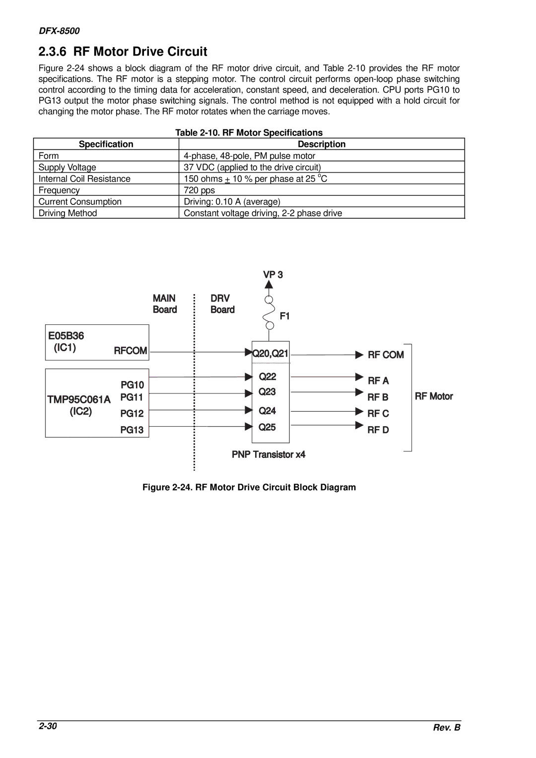
Figure 2-24 shows a block diagram of the RF motor drive circuit, and Table 2-10 provides the RF motor specifications. The RF motor is a stepping motor. The control circuit performs open-loop phase switching control according to the timing data for acceleration, constant speed, and deceleration. CPU ports PG10 to PG13 output the motor phase switching signals. The control method is not equipped with a hold circuit for changing the motor phase. The RF motor rotates when the carriage moves.
| Table | |
Specification |
| Description |
Form |
| |
Supply Voltage |
| 37 VDC (applied to the drive circuit) |
Internal Coil Resistance |
| 150 ohms + 10 % per phase at 25 oC |
Frequency |
| 720 pps |
Current Consumption |
| Driving: 0.10 A (average) |
Driving Method |
| Constant voltage driving, |
|
|
| VP 3 |
|
| MAIN | DRV |
|
|
| Board | Board | F1 |
|
|
|
|
| |
E05B36 |
|
|
|
|
(IC1) | RFCOM |
| Q20,Q21 | RF COM |
|
| |||
|
|
| ||
| PG10 |
| Q22 | RF A |
|
|
| ||
|
| Q23 |
| |
TMP95C061A | PG11 |
| RF B | |
|
| |||
(IC2) | PG12 |
| Q24 | RF C |
| PG13 |
| Q25 | RF D |
|
|
|
RF Motor
PNP Transistor x4
Figure 2-24. RF Motor Drive Circuit Block Diagram
Rev. B |