DSP-100/2000
Users Manual
Split Pairs and NEXT
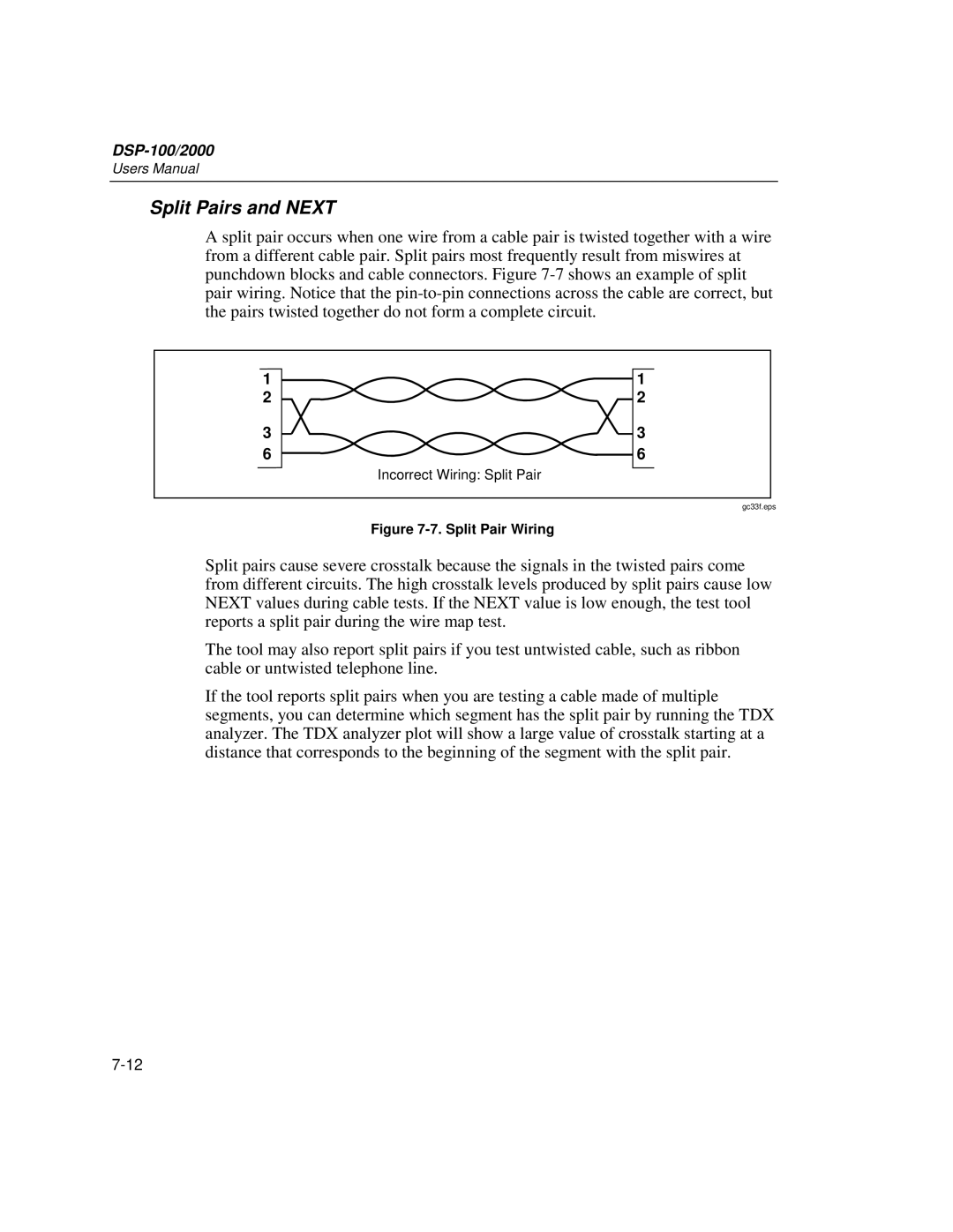
A split pair occurs when one wire from a cable pair is twisted together with a wire from a different cable pair. Split pairs most frequently result from miswires at punchdown blocks and cable connectors. Figure
1 | 1 |
2 | 2 |
3 | 3 |
6 | 6 |
| Incorrect Wiring: Split Pair |
gc33f.eps
Figure 7-7. Split Pair Wiring
Split pairs cause severe crosstalk because the signals in the twisted pairs come from different circuits. The high crosstalk levels produced by split pairs cause low NEXT values during cable tests. If the NEXT value is low enough, the test tool reports a split pair during the wire map test.
The tool may also report split pairs if you test untwisted cable, such as ribbon cable or untwisted telephone line.
If the tool reports split pairs when you are testing a cable made of multiple segments, you can determine which segment has the split pair by running the TDX analyzer. The TDX analyzer plot will show a large value of crosstalk starting at a distance that corresponds to the beginning of the segment with the split pair.
