Getting Started 2
Main Unit Features
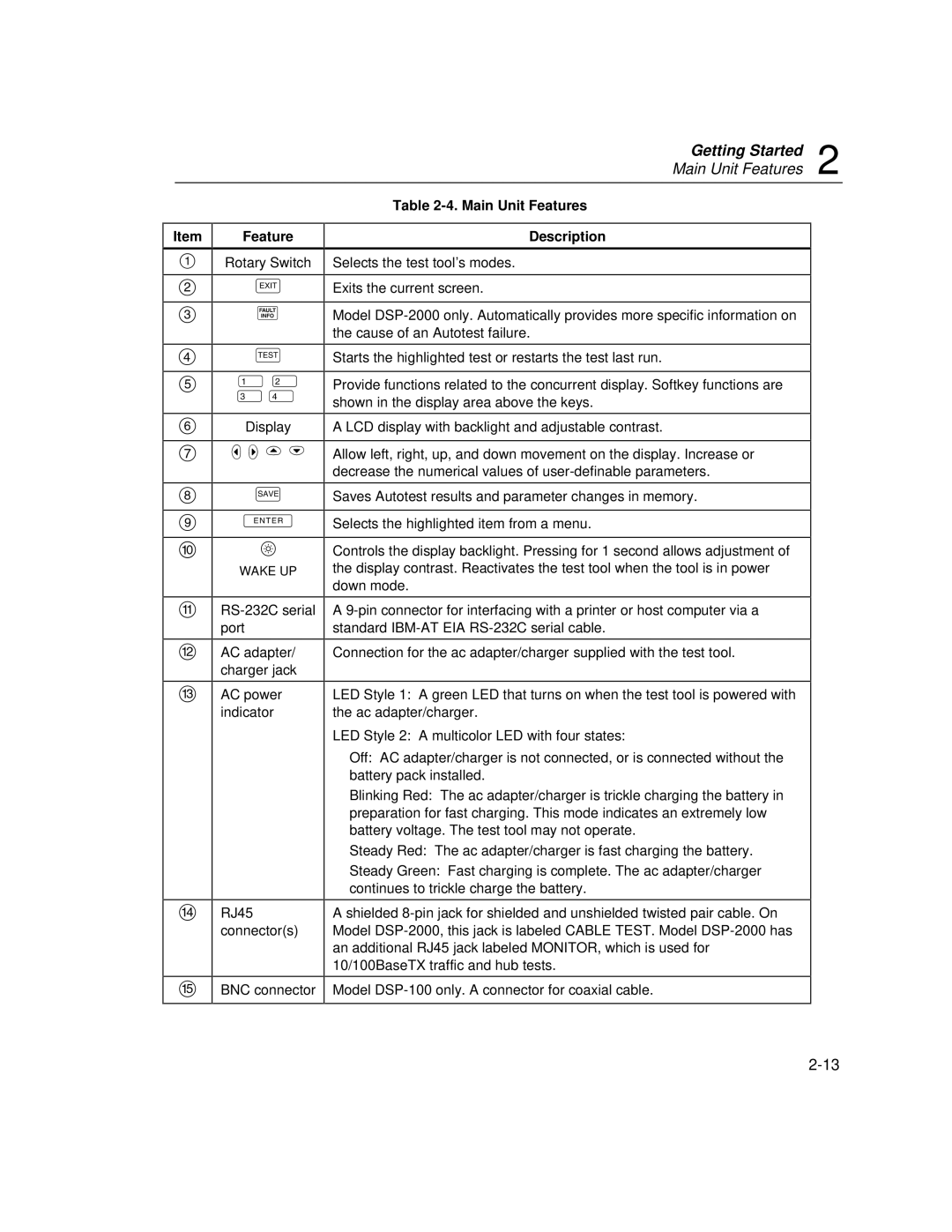
Item
1
2
3
4
5
6
7
8
9
0
f
g
h
i
j
Feature
Rotary Switch
e
F
T
!@
#$
Display
L R U D
S
E
C
WAKE UP
AC adapter/ charger jack
AC power indicator
RJ45
connector(s)
BNC connector
Table 2-4. Main Unit Features
Description
Selects the test tool’s modes.
Exits the current screen.
Model
Starts the highlighted test or restarts the test last run.
Provide functions related to the concurrent display. Softkey functions are shown in the display area above the keys.
A LCD display with backlight and adjustable contrast.
Allow left, right, up, and down movement on the display. Increase or decrease the numerical values of
Saves Autotest results and parameter changes in memory.
Selects the highlighted item from a menu.
Controls the display backlight. Pressing for 1 second allows adjustment of the display contrast. Reactivates the test tool when the tool is in power down mode.
A
Connection for the ac adapter/charger supplied with the test tool.
LED Style 1: A green LED that turns on when the test tool is powered with the ac adapter/charger.
LED Style 2: A multicolor LED with four states:
Off: AC adapter/charger is not connected, or is connected without the battery pack installed.
Blinking Red: The ac adapter/charger is trickle charging the battery in preparation for fast charging. This mode indicates an extremely low battery voltage. The test tool may not operate.
Steady Red: The ac adapter/charger is fast charging the battery.
Steady Green: Fast charging is complete. The ac adapter/charger continues to trickle charge the battery.
A shielded
Model