MC68HC908MR32 MC68HC908MR16
Page
MC68HC908MR32 MC68HC908MR16 Data Sheet, Rev
Data Sheet
MC68HC908MR32 MC68HC908MR16
Revision History
Revision History
Date Revision Description Level Numbers
List of Chapters
List of Chapters MC68HC908MR32 MC68HC908MR16 Data Sheet, Rev
Table of Contents
Chapter Analog-to-Digital Converter ADC
Table of Contents
Chapter Clock Generator Module CGM
Chapter Computer Operating Properly COP
Chapter Configuration Register Config
Chapter External Interrupt IRQ
Chapter Central Processor Unit CPU
Chapter Low-Voltage Inhibit LVI
Chapter Input/Output I/O Ports Ports
Chapter Power-On Reset POR
Chapter Pulse-Width Modulator for Motor Control Pwmmc
Chapter Serial Communications Interface Module SCI
Chapter Serial Peripheral Interface Module SPI
Chapter System Integration Module SIM
Chapter Timer Interface a Tima
Chapter Development Support
Chapter Timer Interface B Timb
Chapter Ordering Information and Mechanical Specifications
Chapter Electrical Specifications
Chapter General Description
Features
Introduction
General Description
MCU Block Diagram
MCU Block
Diagram
Pin QFP Pin Assignments
Pin Assignments
Pin Assignments
Pin Sdip Pin Assignments
Oscillator Pins OSC1 and OSC2
Power Supply Pins VDD and VSS
External Reset Pin RST
CGM Power Supply Pins Vdda and Vssad
Port a Input/Output I/O Pins PTA7-PTA0
Analog Power Supply Pins Vddad and Vssad
Port B I/O Pins PTB7/ATD7-PTB0/ATD0
Port C I/O Pins PTC6-PTC2 and PTC1/ATD9-PTC0/ATD8
PWM Ground Pin Pwmgnd
Port F I/O Pins PTF5/TxD-PTF4/RxD and PTF3/MISO-PTF0/SPSCK
Unimplemented Memory Locations
Chapter Memory
Reserved Memory Locations
Memory Map
I/O Section
Memory
Memory Map
MC68HC908MR32 Memory Map
Memory Addr
Control, Status, and Data Registers Summary Sheet 1
Memory Map Addr Register Name Bit
Control, Status, and Data Registers Summary Sheet 2
Memory Addr Register Name
Control, Status, and Data Registers Summary Sheet 3
Control, Status, and Data Registers Summary Sheet 4
Memory Addr Register Name Bit
Control, Status, and Data Registers Summary Sheet 5
Addr Register Name
Control, Status, and Data Registers Summary Sheet 6
Control, Status, and Data Registers Summary Sheet 7
Control, Status, and Data Registers Summary Sheet 8
Address Vector Low
Vector Addresses
Monitor ROM
Random-Access Memory RAM
Monitor ROM
Address Vector
Flash Control Register
Flash Memory Flash
Flash Page Erase Operation
Hven High-Voltage Enable Bit
Mass Mass Erase Control Bit
Erase Erase Control Bit
Flash Mass Erase Operation
Only bytes which are currently $FF may be programmed
Flash Program Operation
Flash Programming Flowchart
Flash Block Protect Register
Flash Block Protection
Stop Mode
Wait Mode
Examples of Protect Start Address
Functional Description
Chapter Analog-to-Digital Converter ADC
Analog-to-Digital Converter ADC
Block Diagram Highlighting ADC Block and Pins
Voltage Conversion
ADC Port I/O Pins
Functional Description
Continuous Conversion
Conversion Time
Result Justification
Monotonicity
Bit Truncation Mode Error
I/O Signals
Wait Mode
Interrupts
ADC Voltage In Advin
I/O Registers
ADC External Connections
6.2 ANx
ADC Status and Control Register
Aien ADC Interrupt Enable Bit
Input Select
Mux Channel Select
ADC Data Register Low
ADC Data Register High
ADC Clock Divide Ratio
ADC Clock Register
ADC Clock Rate
Analog-to-Digital Converter ADC
Cgmvclk
Chapter Clock Generator Module CGM
Clock Generator Module CGM
CGM Block Diagram
Crystal Oscillator Circuit
Phase-Locked Loop Circuit PLL
PLL Circuits
Manual and Automatic PLL Bandwidth Modes
Acquisition and Tracking Modes
Variable Definitions
Programming the PLL
Variable Definition
Special Programming Exceptions
Base Clock Selector Circuit
CGM External Connections
CGM External Connections
Oscillator Enable Signal Simoscen
PLL Analog Power Pin Vdda
Crystal Amplifier Input Pin OSC1
Crystal Amplifier Output Pin OSC2
CGM Registers
Crystal Output Frequency Signal Cgmxclk
CGM Base Clock Output Cgmout
CGM CPU Interrupt Cgmint
Pllf PLL Interrupt Flag
PLL Control Register
Pllon PLL On Bit
BCS Base Clock Select Bit
ACQ Acquisition Mode Bit
Lock Lock Indicator Bit
PLL Bandwidth Control Register
PCTL30 Unimplemented Bits
XLD Crystal Loss Detect Bit
PLL Programming Register
PBWC30 Reserved for Test
VCO Frequency Multiplier N Selection
Interrupts
VRS74 VCO Range Select Bits
Acquisition/Lock Time Definitions
Acquisition/Lock Time Specifications
Parametric Influences on Reaction Time
Choosing a Filter Capacitor
Acquisition/Lock Time Specifications
Reaction Time Calculation
Frequency
Chapter Configuration Register Config
Configuration Register
Chapter Computer Operating Properly COP
COP Block Diagram
Internal Reset
Power-On Reset
Reset Vector Fetch
Copctl Write
Stop Mode
Monitor Mode
Copd COP Disable
COP Control Register
Freescale Semiconductor
CPU Registers
Chapter Central Processor Unit CPU
Index Register
Accumulator
Central Processor Unit CPU
Program Counter
Stack Pointer
CPU Registers
Half-Carry Flag
Condition Code Register
Interrupt Mask
Negative Flag
Arithmetic/Logic Unit ALU
Low-Power Modes
CPU During Break Interrupts
Zero Flag
Instruction Set Summary Sheet 1
Instruction Set Summary
Instruction Set Summary
Instruction Set Summary Sheet 2
Source Operation Description On CCR Form
Dbnz opr,rel
Instruction Set Summary Sheet 3
JMP ,X
Instruction Set Summary Sheet 4
Operation Description On CCR Form
Instruction Set Summary Sheet 5
Instruction Set Summary Sheet 6
Opcode Map
Opcode Map
9ED 9EE
Opcode Map
Chapter External Interrupt IRQ
IRQ Module Block Diagram
External Interrupt IRQ
IRQ Pin
IRQ Pin
IRQ Interrupt Flowchart
IRQ Status and Control Register Iscr
IRQ Status and Control Register
IRQ Status and Control Register
Irqf IRQ Flag
Freescale Semiconductor
Chapter Low-Voltage Inhibit LVI
LVI Module Block Diagram
False Reset Protection
Forced Reset Operation
Polled LVI Operation
LVI Trip Selection
LVI Interrupts
LVI Status and Control Register
Lviout Bit Indication
LVI Status and Control Register
100 Freescale Semiconductor
I/O Port Register Summary
Chapter Input/Output I/O Ports Ports
Input/Output I/O Ports Ports Addr Register Name
Port a Data Register
Port a
Data Direction Register a
Port a
Port B Data Register
Port B
Port a Pin Functions
Input/Output I/O Ports Ports
Port B Pin Functions
Data Direction Register B
Port B
Port C Data Register
Port C
Data Direction Register C
Port C Pin Functions
Port D
Port D
PTC60
Port E
PTD Bit Pin Mode Accesses to PTD Read
Port E Data Register
Port D Pin Functions
Data Direction Register E
Ddre Bit PTE Bit Pin Mode Accesses to Ddre Accesses to PTE
Port E Pin Functions
Port E
Port F Data Register
Port F
Data Direction Register F
Port F
Port F Pin Functions
112 Freescale Semiconductor
Chapter Power-On Reset POR
114 Freescale Semiconductor
Chapter Pulse-Width Modulator for Motor Control Pwmmc
Pulse-Width Modulator for Motor Control Pwmmc
Block Diagram Highlighting Pwmmc Block and Pins
Features
PWM Module Block Diagram
Register Summary Sheet 2
Register Summary Sheet 3
Features Addr Register Name Bit
Timebase
Resolution
Timebase
Edge-Aligned PWM Positive Polarity
Prescaler
PWM Generators
Load Operation
PWM Prescaler
PWM Interrupt Requests
Reload Frequency Change
Center-Aligned PWM Value Loading
PWM Data Overflow and Underflow Conditions
PWM Data Overflow and Underflow Conditions
PWMVALxHPWMVALxL Condition PWM Value Used
Output Control
12. Complementary Pairing
Output Control
Dead-Time Insertion
14. Dead-Time Generators
15. Effects of Dead-Time Insertion
17. Dead-Time and Small Pulse Widths
Current Voltage On Current
Current Sense Pins
Current Correction Bits Correction Method ISENS1 and ISENS0
Correction Methods
20. Top/Bottom Correction for PWMs 1
Output Polarity
21. PWM Polarity
PWM Output Port Control
OUTx Bit Complementary Mode Independent Mode
OUTx Bits
23. Dead-Time Insertion During Outctl =
Fault Condition Input Pins
Fault Protection
Fault Protection
26. PWM Disabling Scheme
Automatic Mode
Fault Pin Filter
Manual Mode
28. PWM Disabling in Automatic Mode
Output Port Control
Software Output Disable
Initialization and the Pwmen Bit
32. Pwmen and PWM Pins
PWM Operation in Wait Mode
PWM Operation in Wait Mode
Control Logic Block
PWM Counter Registers
35. PWM Counter Modulo Register High Pmodh
PWM Counter Modulo Registers
Control Logic Block
PWMx Value Registers
Pwmint PWM Interrupt Enable Bit
Disy Software Disable Bit for Bank Y Bit
PWM Control Register
Pwmf PWM Reload Flag
LDOK- Load OK Bit
Pwmen PWM Module Enable Bit
IPOL1 Top/Bottom Correction Bit for PWM Pair 1 PWMs 1
IPOL3 Top/Bottom Correction Bit for PWM Pair 3 PWMs 5
IPOL2 Top/Bottom Correction Bit for PWM Pair 2 PWMs 3
PRSC1 and PRSC0 PWM Prescaler Bits
Fault Control Register
PWM Disable Mapping Write-Once Register
Dead-Time Write-Once Register
FINT2 Fault 2 Interrupt Enable Bit
FINT3 Fault 3 Interrupt Enable Bit
FINT1 Fault 1 Interrupt Enable Bit
Fault Status Register
Fault Acknowledge Register
DT2 Dead-Time 2 Bit
PWM Output Control Register
DT1 Dead-Time 1 Bit
10. OUTx Bits
PWM Glossary
PWM Glossary
48. PWM Load Cycle/Frequency Definition
Chapter Serial Communications Interface Module SCI
Serial Communications Interface Module SCI
Block Diagram Highlighting SCI Block and Pins
SCI Module Block Diagram
Serial Communications Interface Module SCI Addr
Data Format
SCI Transmitter
Transmitter
Character Transmission
Character Length
Break Characters
Idle Characters
Receiver
Inversion of Transmitted Output
Transmitter Interrupts
SCI Receiver Block Diagram
Data Sampling
Character Reception
Stop Bit Recovery
Data Bit Recovery
Start Bit Verification
Error Interrupts
Framing Errors
Receiver Wakeup
Receiver Interrupts
SCI During Break Module Interrupts
13.6 I/O Signals
13.6.1 PTF5/TxD Transmit Data
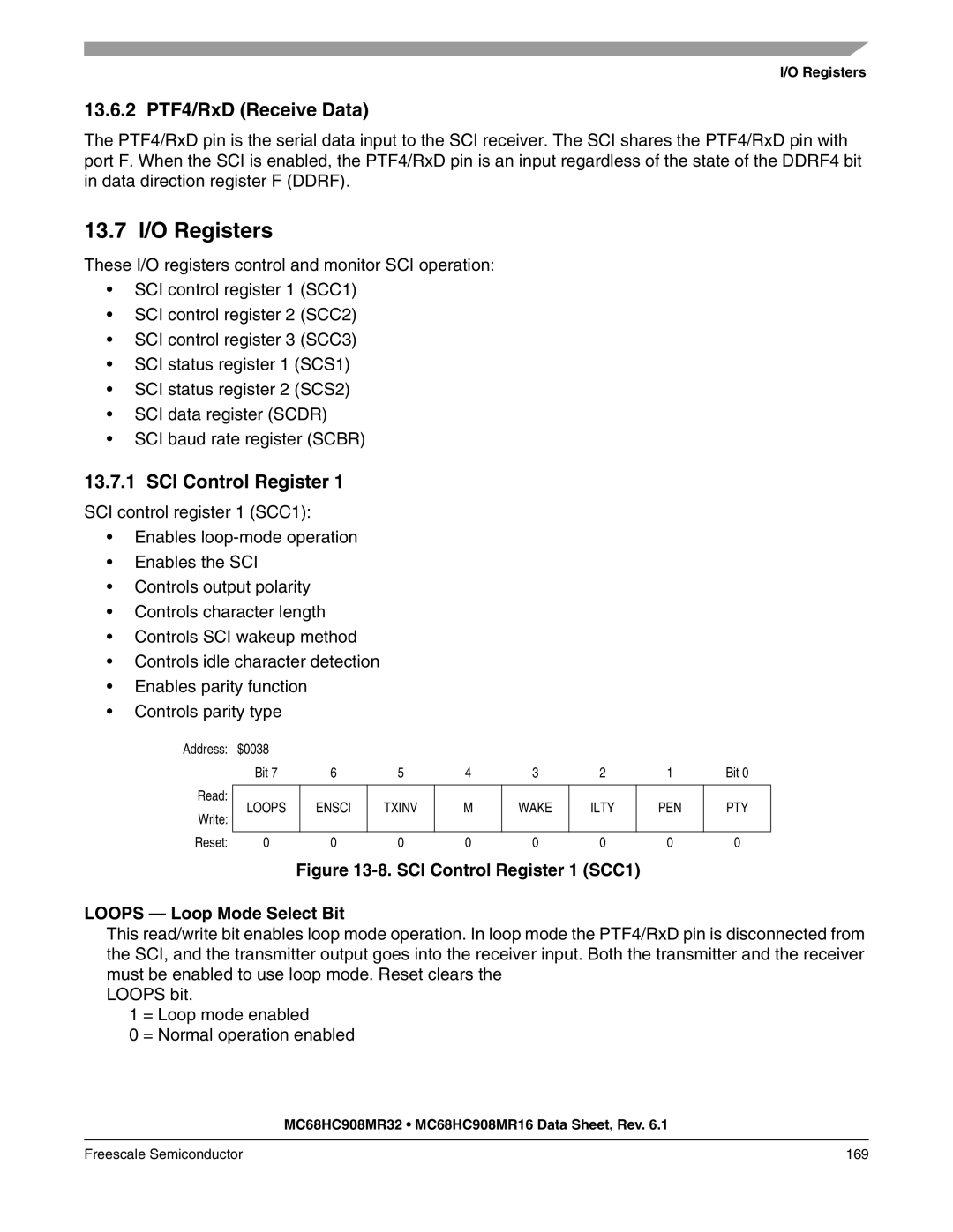
13.6.2 PTF4/RxD Receive Data
13.7 I/O Registers
SCI Control Register
Mode Character Length Bit
Ensci Enable SCI Bit
PEN Parity Enable Bit
Txinv Transmit Inversion Bit
Character Format Selection
Tcie Transmission Complete Interrupt Enable Bit
Control Bits Character Format
Start Data Parity Stop
Ilie Idle Line Interrupt Enable Bit
Scrie SCI Receive Interrupt Enable Bit
TE Transmitter Enable Bit
RE Receiver Enable Bit
Neie Receiver Noise Error Interrupt Enable Bit
Orie Receiver Overrun Interrupt Enable Bit
Feie Receiver Framing Error Interrupt Enable Bit
Peie Receiver Parity Error Interrupt Enable Bit
TC Transmission Complete Bit
SCI Status Register
Scrf SCI Receiver Full Bit
Or Receiver Overrun Bit
Idle Receiver Idle Bit
PE Receiver Parity Error Bit
FE Receiver Framing Error Bit
NF Receiver Noise Flag Bit
SCI Baud Rate Register
SCI Data Register
RPF -Reception-in-Progress Flag
SCI Baud Rate Prescaling
Baud Rate Divisor BD
SCI Baud Rate Selection
Baud Rate Divisor PD Divisor BD
SCI Baud Rate Selection Examples
180 Freescale Semiconductor
Signal Name Description
Signal Name Conventions
Chapter System Integration Module SIM
SIM Bus Clock Control and Generation
Clock Startup from POR or LVI Reset
Bus Timing
System Integration Module SIM
Clocks in Wait Mode
Reset and System Initialization
External Pin Reset
Reset and System Initialization
Reset Type Number of Cycles Required to Set PIN
Active Resets from Internal Sources
PIN Bit Set Timing
Computer Operating Properly COP Reset
Power-On Reset POR
SIM Counter and Reset States
SIM Counter During Power-On Reset
SIM Counter
Interrupts
Exception Control
Exception Control
Interrupt Processing
Hardware Interrupts
Interrupt Recovery
Reset
Low-Power Mode
Software Interrupt SWI Instruction
SIM Break Status Register
SIM Registers
SIM Registers
PIN External Reset Bit
SIM Reset Status Register
Ilop Illegal Opcode Reset Bit
Ilad Illegal Address Reset Bit opcode fetches only
SIM Break Flag Control Register
194 Freescale Semiconductor
Pin Name Conventions
Chapter Serial Peripheral Interface Module SPI
Pin Name Conventions
Serial Peripheral Interface Module SPI
Block Diagram Highlighting SPI Block and Pins
SPI Module Block Diagram
Serial Peripheral Interface Module SPI Addr
Master Mode
Clock Phase and Polarity Controls
Slave Mode
Transmission Formats
Transmission Formats
Transmission Format Cpha =
Transmission Format When Cpha =
Transmission Initiation Latency
Transmission Start Delay Master
Overflow Error
Error Conditions
Error Conditions
10. Clearing Sprf When Ovrf Interrupt Is Not Enabled
Mode Fault Error
Freescale Semiconductor 205
Flag Request
SPI Interrupts
Resetting the SPI
Resetting the SPI
Queuing Transmission Data
12. SPRF/SPTE CPU Interrupt Timing
15.11 I/O Signals
Miso Master In/Slave Out
Signals
Mosi Master Out/Slave
Spsck Serial Clock
SPI Configuration State of SS Logic
SPI Configuration
15.12 I/O Registers
VSS Clock Ground
Spwom SPI Wired-OR Mode Bit
Cpha Clock Phase Bit
Spmstr SPI Master Bit
Cpol Clock Polarity Bit
SPTIE- SPI Transmit Interrupt Enable Bit
SPE SPI Enable Bit
Errie Error Interrupt Enable Bit
SPI Status and Control Register
Modfen Mode Fault Enable Bit
Modf Mode Fault Bit
Ovrf Overflow Bit
Spte SPI Transmitter Empty Bit
SPI Master Baud Rate Selection
SPI Data Register
2is a block diagram of the Tima
Chapter Timer Interface a Tima
Timer Interface a Tima
Block Diagram Highlighting Tima Block and Pins
Tima Block Diagram
TIM I/O Register Summary
Timer Interface a Tima Addr Register Name Bit
Input Capture
Tima Counter Prescaler
Unbuffered Output Compare
Output Compare
Buffered Output Compare
Pulse-Width Modulation PWM
PWM Period and Pulse Width
Unbuffered PWM Signal Generation
PWM Initialization
Buffered PWM Signal Generation
224 Freescale Semiconductor
Tima Channel I/O Pins PTE4/TCH0A-PTE7/TCH3A
16.6 I/O Signals
16.7 I/O Registers
Tima Clock Pin PTE3/TCLKA
Trst Tima Reset Bit
Toie Tima Overflow Interrupt Enable Bit
Tstop Tima Stop Bit
PS20 Prescaler Select Bits
Tima Counter Registers
Prescaler Selection
PS20 Tima Clock Source
Tima Channel Status and Control Registers
Tima Counter Modulo Registers
CHxIE Channel x Interrupt Enable Bit
MSxA Mode Select Bit a
MSxB Mode Select Bit B
ELSxB and ELSxA Edge/Level Select Bits
Mode, Edge, and Level Selection
MSxBMSxA ELSxBELSxA Mode Configuration
TOVx Toggle-On-Overflow Bit
CHxMAX Channel x Maximum Duty Cycle Bit
10. Tima Channel Registers
Tima Channel Registers
10. Tima Channel Registers TACH0H/L-TACH3H/L
234 Freescale Semiconductor
Timb module is not available in the 56-pin Sdip
Chapter Timer Interface B Timb
Timer Interface B Timb
Block Diagram Highlighting Timb Block and Pins
Timb Block Diagram
Timb Counter Prescaler
Timer Interface B Timb Addr Register Name Bit
Freescale Semiconductor 239
240 Freescale Semiconductor
Freescale Semiconductor 241
242 Freescale Semiconductor
Timb Channel I/O Pins PTE1/TCH0B-PTE2/TCH1B
17.6 I/O Signals
Timb Clock Pin PTE0/TCLKB
17.7 I/O Registers
Toie Timb Overflow Interrupt Enable Bit
Timb Status and Control Register
Tstop Timb Stop Bit
Trst Timb Reset Bit
PS20 Timb Clock Source
Timb Counter Modulo Registers
Timb Counter Registers
Timb Channel Status and Control Registers
248 Freescale Semiconductor
PWM
10. Timb Channel Registers TBCH0H/L-TBCH1H/L
Timb Channel Registers
Break Module BRK
Chapter Development Support
Functional Description
Flag Protection During Break Interrupts
Development Support
Break Module Block Diagram
Break Module Registers
Low-Power Modes
Brka Break Active Bit
Break Status and Control Register
Break Address Registers
Break Status Register
Monitor ROM MON
Break Flag Control Register
Monitor ROM MON
Mode Differences
Entering Monitor Mode
Normal Monitor Mode
Monitor Mode Circuit
$FFFF
Monitor Mode Signal Requirements and Options
Data Format
Forced Monitor Mode
Commands
Break Signal
Echoing
Write Write Memory Command
Read Read Memory Command
Iread Indexed Read Command
Command Sequence
Readsp Read Stack Pointer Command
Iwrite Indexed Write Command
RUN Run User Program Command
Baud Rate
Security
Monitor Baud Rate Selection
13. Monitor Mode Entry Timing
Characteristic1 Symbol Value Unit
Chapter Electrical Specifications
Absolute Maximum Ratings
Electrical Specifications
Thermal Characteristics
Characteristic Symbol Value Unit
Functional Operating Range
DC Electrical Characteristics
DC Electrical Characteristics
Characteristic1 Symbol Min Typ2 Max Unit
Characteristic Symbol Min Typ Max Unit
Flash Memory Characteristics
Characteristic Symbol Min Max Unit
Control Timing
Serial Peripheral Interface Characteristics
Serial Peripheral Interface Characteristics
Diagram Characteristic2 Symbol Min Max Unit Number1
SPI Master Timing
SPI Slave Timing
Clock Generation Module Component Specifications
TImer Interface Module Characteristics
Characteristic Symbol Min Typ Max
CGM Operating Conditions
CGM Acquisition/Lock Time Specifications
CGM Acquisition/Lock Time Specifications
Description Symbol Min Typ Max
3FF
Analog-to-Digital Converter ADC Characteristics
Order Numbers
Chapter Ordering Information and Mechanical Specifications
Order Numbers
MC Order Number Operating
20.3 64-Pin Plastic Quad Flat Pack QFP
Ordering Information and Mechanical Specifications
Pin Shrink Dual In-Line Package Sdip
20.4 56-Pin Shrink Dual In-Line Package Sdip
278 Freescale Semiconductor
Appendix a MC68HC908MR16
MC68HC908MR16
Figure A-1. MC68HC908MR16 Memory Map
Page
How to Reach Us