Setting Up the Analyzer
To Unpack the Analyzer
|
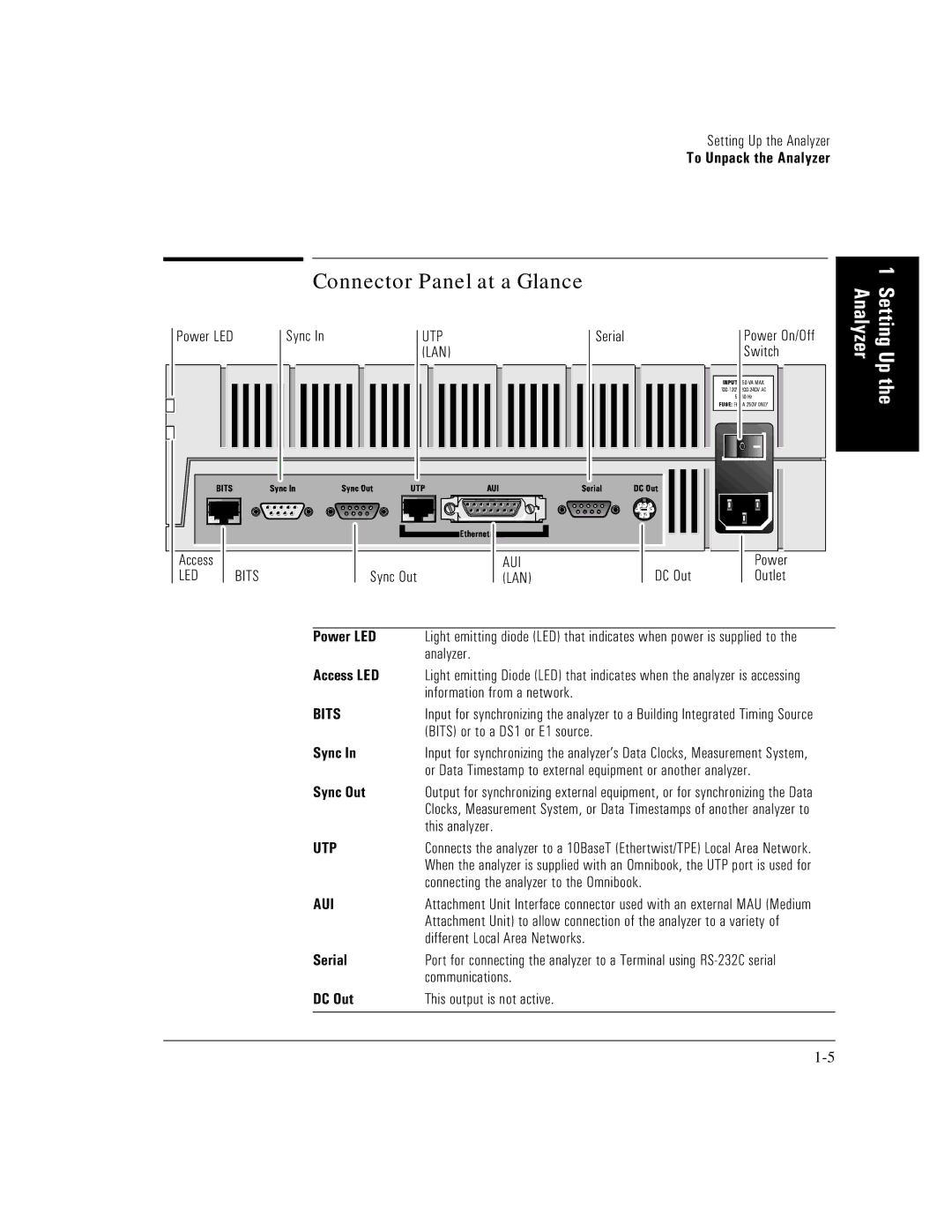
| Connector Panel at a Glance |
|
| |
Power LED |
| Sync In | UTP | Serial | Power On/Off |
|
|
| (LAN) |
| Switch |
Access |
|
| AUI |
| Power |
LED | BITS | Sync Out | (LAN) | DC Out | Outlet |
|
| Power LED | Light emitting diode (LED) that indicates when power is supplied to the | ||
|
|
| analyzer. |
|
|
|
| Access LED | Light emitting Diode (LED) that indicates when the analyzer is accessing | ||
|
|
| information from a network. |
|
|
|
| BITS | Input for synchronizing the analyzer to a Building Integrated Timing Source | ||
|
|
| (BITS) or to a DS1 or E1 source. |
|
|
|
| Sync In | Input for synchronizing the analyzer’s Data Clocks, Measurement System, | ||
|
|
| or Data Timestamp to external equipment or another analyzer. | ||
|
| Sync Out | Output for synchronizing external equipment, or for synchronizing the Data | ||
|
|
| Clocks, Measurement System, or Data Timestamps of another analyzer to | ||
|
|
| this analyzer. |
|
|
|
| UTP | Connects the analyzer to a 10BaseT (Ethertwist/TPE) Local Area Network. | ||
|
|
| When the analyzer is supplied with an Omnibook, the UTP port is used for | ||
|
|
| connecting the analyzer to the Omnibook. |
| |
|
| AUI | Attachment Unit Interface connector used with an external MAU (Medium | ||
|
|
| Attachment Unit) to allow connection of the analyzer to a variety of | ||
|
|
| different Local Area Networks. |
|
|
|
| Serial | Port for connecting the analyzer to a Terminal using | ||
|
|
| communications. |
|
|
|
| DC Out | This output is not active. |
|
|
1 Setting Up the Analyzer