Part number Document version
HP V1910 Switch Series
Warranty
Contents
Page
Page
STP177
Page
Page
Page
Page
Page
Page
Overview
Default login information
Configuration through the web interface
Web-based network management operating environment
Logging in to the web interface
Example
Login page of the web interface
Logging out of the web interface
Web-based configuration interface
Introduction to the web interface
Navigation tree Body area Title area
Introduction to the web-based NM functions
Web user level
Description of Web-based NM functions
Function menu Description User level
Used at the next startup from the host of the current
Snmp
VCT
Rmon
Mstp
Vlan
MAC
Their partner ports
Lacp
Lldp
Igmp
AAA
ARP
CRL
Radius
PKI
Class
Buttons and icons
Introduction to the common items on the web pages
Display
Commonly used buttons and icons
Search function
Content display by pages
Sorting function
Advanced search
Sort display based on MAC address in the ascending order
Configuration guidelines
Setting up the configuration environment
Configuration at the CLI
Getting started with the CLI
Console cable
Network diagram for configuration environment setup
Setting terminal parameters
Set the serial port used by the HyperTerminal connection
Connection description of the HyperTerminal
HyperTerminal window
Set the serial port parameters
Select File Properties in the HyperTerminal window
Press Enter. The Password prompt display
Set terminal emulation in Switch Properties dialog box
Logging in to the CLI
Enter your username at the Username prompt
Initialize
CLI commands
Ipsetup
# Modify the login password of user admin
Password
Password
Quit
Ping
Summary
Reboot
# Display summary information of the device
Upgrade
Network requirements
Configuration procedure
# Reboot the switch
Basic service setup
Configuration wizard
Entering the configuration wizard homepage
Configuring system parameters
Configuring management IP address
Configure IPv4
Admin Status
Configure how the Vlan interface obtains an IPv4 address
Select a Vlan interface
Configuration finishes
Finishing configuration wizard
ItemDescription
Manual Important
Stack management configuration task list
Configuring stack management
Network diagram for stack management
Stack management configuration task list
Configuring global parameters of a stack
Setup Configuration items of global parameters
Return to Stack management configuration task list
Configuring stack ports
Displaying topology summary of a stack
Topology summary Fields of topology summary
Displaying device summary of a stack
Stack configuration example
Logging into a member switch from the master switch
Stack
Configure global parameters for the stack on Switch a
Configure a stack port on Switch a
Configure stack ports on Switch B
Configure a stack port on Switch C
Configuration guidelines
Displaying device summary
Summary
Displaying system information
System information
Basic system information
Displaying device information
System resource state
Recent system operation logs
Device information
Configuring device basic information
Device basic information configuration
Configuring system name
Configuring idle timeout period
Idle timeout Set the idle timeout period for logged-in users
System time configuration
System time configuration
Configuring system time
System time configuration items
System time configuration example
Network diagram for configuring system time
NTP
Configure Device a as the NTP server of Switch B
Configure Device a
Configuration guidelines
Configuring log management
Log management configuration
Configuration task list
Setting syslog related parameters
Displaying syslog
Return to Log management configuration task list
System logs severity level
Display syslog Syslog display items
Severity level Description Value
See
IP address of the loghost
Setting loghost
Set loghost Loghost configuration item
Back up configuration
Configuration management
Restore configuration
Backup configuration
Save configuration confirmation
Save configuration
Configuration restore
Initialize confirmation dialog box
Initialize
Software upgrade
Device maintenance
Extension .bin
Filename
Device reboot
Device reboot
Specifies the type of the startup configuration file
Already exists, overwrite
Diagnostic information
Diagnostic information
Electronic label
Electronic label
Diagnostic information file is created
File management
File management configuration
Displaying file list
File management
Removing a file
Downloading a file
Uploading a file
Configuring a port
Port management configuration
Setting operation parameters for a port
Setup tab
Pvid
Port configuration items
MDI
Input a percentage in the box below
Percentage or by PPS as follows
Constrain
Multicast Suppression Input a number in the box below
Viewing the operation parameters of a port
Details tab
Port management configuration example
Network diagram for port rate configuration
Configure the rate of GigabitEthernet 1/0/4
Batch configure port rate
Display the rate settings of ports
Introduction to port mirroring
Port mirroring configuration
Implementing port mirroring
Local port mirroring
Configuring local port mirroring
Configuring local port mirroring
Local port mirroring configuration task list
Creating a mirroring group
Return to Local port mirroring configuration task list
Configuring ports for a mirroring group
Mirroring ports of a port mirroring group
Local port mirroring configuration example
Configuration examples
Create a local mirroring group
Configuration progress dialog box
Configure the mirroring ports
Configure the monitor port
User management
Add a user Local user configuration items
Managing users
Adding a local user
Super password
Setting the super password
Super password configuration items
Switching to the management level
Switch to the management level
Input are not consistent when you apply the configuration
Loopback operation
Loopback test configuration
Loopback test result
Test the status of the cable connected to an Ethernet port
Testing cable status
Failure
Description on the cable test result
Status and length of the cable
Setting the traffic statistics generating interval
Flow interval configuration
Monitoring port traffic statistics
Viewing port traffic statistics
Port traffic statistics
Configuring storm constrain
Storm constrain configuration
Storm Constrain tab
Configuring storm constrain
∙ None-Performs no action
Upper threshold. Available options include
Upper threshold
Thresholds for at least a type of traffic
After that
Crossed after that
Working mechanism
Rmon configuration
Rmon groups
Alarm group
Ethernet statistics group
History group
Configuring the Rmon statistics function
Configuring Rmon
Rising and falling alarm events
Event group
Rmon statistics group configuration task list
Configuring the Rmon alarm function
Rmon history group configuration task list
TaskRemarks
Rmon alarm configuration task list
Configuring a statistics entry
Displaying Rmon running status
Display Rmon running status
100
Configuring a history entry
Return to Rmon statistics group configuration task list
Return to Rmon history group configuration task list
Configuring an event entry
Buckets Granted
101
Return to Rmon alarm configuration task list
Configuring an alarm entry
None of them is selected, the system will take no action
102
Statics Item
104
Displaying Rmon statistics information
Log-and-trap
Rmon statistics information Fields of Rmon statistics
Return to Display Rmon running status
Displaying Rmon history sampling information
Corresponding to the MIB node etherHistoryCRCAlignErrors
CRCAlignErrors
Number of the entry in the system buffer
Node etherHistoryOctets
Network diagram for Rmon
Rmon configuration example
Displaying Rmon event logs
Log Return to Display Rmon running status
109
110
Display Rmon statistics
111
Configure an event group
Display the index of a event entry
112
Configure an alarm group
PoE Disabled Disable PoE on the port 113
Energy saving configuration
Configuring energy saving on a port
ItemDescription
Snmp mechanism
Snmp configuration
Relationship between an NMS, agent and MIB
MIB tree
Configuring SNMPv1 or SNMPv2c
Snmp configuration
Perform the tasks in 1 to configure SNMPv1 or SNMPv2c
SNMPv1 or SNMPv2c configuration task list
Perform the tasks in 1 to configure SNMPv3
Configuring SNMPv3
SNMPv3 configuration task list
Configuring Snmp trap
Specify to enable or disable Snmp
Set up Configuration items for enabling Snmp
Configure the local engine ID
Local Engine ID
Creating an Snmp view
Configuring an Snmp view
View
Create an Snmp view
Adding rules to an Snmp view
Configuration items for creating an Snmp view
Identify a MIB subtree
Set the subtree mask
Configure an Snmp community Create an Snmp Community
Configuring an Snmp community
Add rules to an Snmp view
121
Configuration items for configuring an Snmp community
Configuring an Snmp group
Return to SNMPv1 or SNMPv2c configuration task list
Snmp group
Return to SNMPv3 configuration task list
Configuring an Snmp user
Objects on the device
Agent
Description
Configuring Snmp trap function
Address in the text box according to the IP address type
Set the destination IP address
Destination IP Address
NMS
Snmp configuration example
Network diagram for Snmp configuration
128
Enable Snmp
129
130
Create an Snmp group
131
Enable the agent to send Snmp traps
Add target hosts of Snmp traps
132
Configuration verification
Displaying interface statistics
Interface statistics
Field Description
Vlan diagram
Vlan configuration
Introduction to Vlan
Vlan fundamentals
Traditional Ethernet frame format
Vlan types
Position and format of Vlan tag
136
Introduction to port-based Vlan
Tag removed or intact depending on your configuration 137
Port link type
Frame
Creating VLANs
Configuring a Vlan
Vlan configuration task list approach
Return to Vlan configuration task list approach
Create tab Configuration items of creating VLANs
Selecting VLANs
139
140
Select Vlan tab Configuration items of selecting VLANs
Modifying a Vlan
Assigned to this Vlan
Modify Vlan tab Configuration items of modifying a Vlan
Aggregate interfaces from this list
141
Modifying ports
Modify Port tab Configuration items of modifying ports
Select the ports to be modified
Untagged
Network diagram for Vlan configuration
Vlan configuration example
144
145
Create Vlan 2, Vlan 6 through Vlan 50, and Vlan
146
Set a Vlan range
147
148
Configuring Vlan interfaces
Vlan interface configuration
Perform the tasks in 1 to configure a Vlan interface
Vlan interface configuration task list
Return to Vlan interface configuration task list
Create tab Configuration items of creating a Vlan interface
Bootp
Modifying a Vlan interface
Select the Vlan interface to be configured
Modify tab Configuration items of modifying a Vlan interface
152
Selected Vlan interface
Is up if one or more Ethernet ports in the Vlan are up
Default OUI addresses of different vendors
Voice Vlan configuration
OUI addresses
Voice Vlan assignment modes
154
Co-relation
Voice Vlan mode Packet type Packet processing mode
Configuring the voice Vlan
Security mode and normal mode of voice VLANs
Adding OUI addresses to the OUI list
Configuring voice Vlan globally
Configuring voice Vlan on a port
Configuring voice Vlan on a port
Configuring voice Vlan globally
Configure voice Vlan Global voice Vlan configuration items
Timer expires, the port is removed from the voice Vlan
Be configured as the voice Vlan
Set the voice Vlan assignment mode of a port
Voice Vlan function on the port
Set the voice Vlan ID
159
Adding OUI addresses to the OUI list
160
Voice Vlan configuration examples
161
Create Vlan
162
Configure GigabitEthernet 1/0/1 as a hybrid port
163
Configure the voice Vlan function globally
Add OUI addresses to the OUI list
Verify the configuration
Current OUI list of the device
164
165
Current voice Vlan information
166
167
168
Assign GigabitEthernet 1/0/1 to Vlan 2 as an untagged member
169
Configure voice Vlan on GigabitEthernet 1/0/1
170
171
172
MAC address configuration
Configuring a MAC address entry
Configuring MAC addresses
MAC address table of the device
173
Click Add in the bottom to enter the page as shown in b
MAC tab
Create a MAC address entry
174
Configuration items of creating a MAC address entry
Setting the aging time of MAC address entries
Set the ID of the Vlan to which the MAC address belongs
Port Set the port to which the MAC address belongs
176
MAC address configuration example
Create a static MAC address entry
STP protocol packets
Mstp configuration
Basic concepts in STP
Root bridge
Designated bridge and designated port
How STP works
Path cost
Description of designated bridges and designated ports
Step Actions
Selection of the optimum configuration Bpdu
Calculation process of the STP algorithm
180
Selection of the root port and designated ports
Step Description
Initial state of each device
Network diagram for the STP algorithm
Device Port name Bpdu of port
∙ Comparison process and result on each device
0, 1, BP2 before the configuration Bpdu is updated
BP2 with the configuration Bpdu of BP2. If the calculated
Bpdu
CP2 1, 0, 1, BP2
Final calculated spanning tree
Configuration Bpdu forwarding mechanism in STP
Blocked port CP2 0, 0, 0, AP2 Root port CP2 0, 5, 1, BP2
183
184
STP timers
STP and Rstp limitations
Mstp features
Mstp basic concepts
185
VLAN-to-MSTI mapping table
MST region
Basic concepts in Mstp
186
Common root bridge
Regional root
Boundary port
Port roles
188
Port states
Port roles
Implementation of Mstp on devices
How Mstp works
Cist calculation
Msti calculation
Configuring an MST region
Configuring Mstp
Perform the tasks described in 1 to configure Mstp
Mstp configuration task list
MST region
Return to Mstp configuration task list
Click Modify to enter the page shown in b
Vlan ID
Configuring Mstp globally
∙ STP-Each port on a device sends out STP BPDUs
Set the STP working mode
Number of devices on the path composed of the most devices
Bridge Diameter
STP
Configuring Mstp on a port
Manually configure path cost for ports
Set the type of protection to be enabled on the port
Configuration may cause a temporary loop
Recommends you to use the default value
Protection type Description
Displaying Mstp information of a port
Protection types
Forwarding
Port Summary tab
Learning
Discarding
Whether or not the port is an edge port
199
Mstp configuration example
Network diagram for Mstp configuration
Region tab
Configure an MST region
∙ Click Modify to enter the page shown in c
200
201
Configure Mstp globally on Switch a
202
203
Configure Mstp globally on Switch D
When configuring MSTP, follow these guidelines
Page
Basic concepts
Link aggregation and Lacp configuration
Aggregate interface
Aggregation group
Static aggregation mode
Class-two configurations
Class-two configurations
Link aggregation modes
207
Dynamic aggregation mode
Load sharing mode of an aggregation group
Configuring link aggregation and Lacp
Configuring a static aggregation group
Configuring a dynamic aggregation group
Setting Lacp priority
Dynamic aggregation group configuration task list
Displaying information of LACP-enabled ports
Creating a link aggregation group
210
Assign an ID to the link aggregation group to be created
Displaying information of an aggregate interface
Setting Lacp priority
Lacp priority configuration items
Displaying information of LACP-enabled ports
Also on LACP-disabled ports
System Priority Set the Lacp priority of the local system
Field/button Description
Display information about LACP-enabled ports
Fields in the LACP-enabled port summary table
Fields in the Partner Port Details table
Link aggregation and Lacp configuration example
Describes the fields in the Partner Port Details table
Create static link aggregation group
Network diagram for static link aggregation configuration
∙ Set the link aggregation interface ID to
215
216
Create dynamic link aggregation group
217
Background
Lldp configuration
LLDPDUs
Lldpdu
SNAP-encapsulated Lldpdu format
TLVs
Lldpdu encapsulation format
FCS
Type Description Remarks
Basic Lldp TLVs
Ieee 802.1 organizationally specific TLVs
Ieee 802.1 organizationally specific TLVs
Ieee 802.3 organizationally specific TLVs
LLDP-MED TLVs
Ieee 802.3 organizationally specific TLVs
LLDP-MED TLVs
Compatibility of Lldp with CDP
How Lldp works
Lldp configuration task list
Configuring Lldp
Perform the tasks in 1 to configure Lldp
Lldp configuration task list
224
Enabling Lldp on ports
Task Remarks
225
Configuring Lldp settings on ports
Port Setup tab Return to Lldp configuration task list
226
For modifying Lldp settings on a port
Is Ethernet
CDP Operating Mode
∙ Disable-Neither sends nor receives CDPDUs
CDP operating mode on the port to TxRx
Enable Lldp polling and set the polling interval
DOT3 TLV MAC/PHY
Configuring global Lldp setup
Global Setup tab Global Lldp setup configuration items
Displaying Lldp information for a port
Port component
Port ID type
Interface alias
Chassis ID type
Type of PSE power source advertised by the local device
Chassis component
233
Endpoint devices
Link aggregation group
III endpoint devices are used directly by end users
234
Unknown
236
Displaying global Lldp information
Global Summary tab Global Lldp information
Basic Lldp configuration example
Lldp configuration examples
Neighbor Summary tab Return to Lldp configuration task list
Displaying Lldp information received from Lldp neighbors
239
Network diagram for basic Lldp configuration
240
Port Setup tab
241
For setting Lldp on multiple ports
242
Global Setup tab
243
For configuring Lldp on the selected port
244
CDP-compatible Lldp configuration example
245
Network diagram for CDP-compatible Lldp configuration
For creating VLANs
246
For configuring ports
247
For configuring the voice Vlan function on ports
248
249
For modifying Lldp settings on ports
250
Principle of Igmp snooping
Igmp snooping configuration
Igmp snooping related ports
Multicast forwarding before and after Igmp snooping runs
Work mechanism of Igmp snooping
When receiving a general query
Igmp snooping related ports
252
253
When receiving a membership report
When receiving a leave group message
254
Configuring Igmp snooping
Igmp snooping querier
Enabling Igmp snooping globally
Basic Igmp snooping configurations
Return to Configuration task list
Configuring Igmp snooping in a Vlan
Igmp snooping configuration items
Advanced configuration
Configuring Igmp snooping port functions
Group Limit
Configuration items for advanced Igmp snooping features
Display Igmp snooping multicast entry information
259
Igmp snooping configuration example
ID of the Vlan to which the entry belongs
260
Network diagram for Igmp snooping configuration
261
262
Add a port to the Vlan
263
Enable Igmp snooping globally
Configure Igmp snooping in the Vlan
264
Configure Igmp snooping on GigabitEthernet 1/0/3
Igmp snooping multicast entry information displaying
265
Details about an Igmp snooping multicast entry
Routing table
Routing configuration
Static route
266
Default route
Configuring IPv4 routing
Displaying the IPv4 active route table
Address will be forwarded out the interface
Specify the mask of the destination IP address
Preferences enables route backup
Creating an IPv4 static route
Configuration outlines
Static route configuration example
Network diagram for IPv4 static route configuration
Select the output interface
270
Configure a default route
271
Configure a static route
272
273
Precautions
Introduction to Dhcp
Dhcp overview
Dhcp address allocation
Allocation mechanisms
IP address lease extension
Dynamic IP address allocation process
Dynamic IP address allocation process
275
276
Dhcp message format
Dhcp message format
Dhcp options overview
Dhcp options
Introduction to Dhcp options
Introduction to Option
Sub-option 1 in normal padding format
Protocols and standards
Sub-option 2 in normal padding format
278
Introduction to Dhcp relay agent
Dhcp relay agent configuration
Application environment
Fundamentals
Dhcp relay agent work process
Dhcp relay agent configuration task list
281
Dhcp relay agent configuration
Configuring and displaying clients IP-to-MAC bindings
Create a server group
Return to Dhcp relay agent configuration task list
Creating a Dhcp server group
283
Dhcp server group configuration items
Enabling the Dhcp relay agent on an interface
284
Configuring and displaying clients IP-to-MAC bindings
285
Dhcp relay agent configuration example
Network diagram for Dhcp relay agent configuration
286
Enable Dhcp
287
Dhcp snooping overview
Dhcp snooping configuration
Functions of Dhcp snooping
Recording IP-to-MAC mappings of Dhcp clients
Configuring trusted ports in a cascaded network
Configuring a trusted port connected to a Dhcp server
Configure trusted and untrusted ports
Configure trusted ports in a cascaded network
Dhcp snooping support for Option
Dhcp snooping configuration task list
Describes roles of the ports shown in a
Roles of ports
Enabling Dhcp snooping
Configuring Dhcp snooping
Functions on an interface
Displaying clients IP-to-MAC
292
Dhcp snooping configuration
Return to Dhcp snooping configuration task list
Displaying clients IP-to-MAC bindings
Configuring Dhcp snooping functions on an interface
Include
Option 82 padded in normal format
294
Dhcp snooping configuration example
This field displays the Vlan to which the device belongs
295
Network diagram for Dhcp snooping configuration
296
Enable Dhcp snooping
297
Configure Dhcp snooping functions on GigabitEthernet 1/0/1
Configure Dhcp snooping functions on GigabitEthernet 1/0/2
298
Configure Dhcp snooping functions on GigabitEthernet 1/0/3
Service management configuration
Service management Service management configuration items
Configuring service management
Https
Trace route diagram
Diagnostic tools
Trace route
302
Ping configuration
Diagnostic tool operations
Ping operation
303
Trace route operation
Trace route configuration
Ping operation result
304
305
Trace route operation result
ARP overview
ARP management
ARP function
ARP message format
ARP operation
ARP address resolution process
ARP table
307
Managing ARP entries
ARP Table configuration
Displaying ARP entries
Dynamic ARP entry
Describes the static ARP entry configuration items
Static ARP configuration example
Static ARP entry configuration items
Creating a static ARP entry
310
Network diagram for configuring static ARP entries
311
∙ After the configuration process is complete, click Close
Add GigabitEthernet 1/0/1 to Vlan
312
Create VLAN-interface
Gratuitous ARP
Configuring gratuitous ARP
Introduction to gratuitous ARP
Create a static ARP entry
Packets
Enabled by default
Learning function
Period
ARP detection
ARP attack defense configuration
Introduction to ARP detection
Man-in-the-middle attack
316
ARP detection mechanism
Man-in-the-middle attack
317
Configuring ARP detection
ItemDescription
Creating a static binding entry
Configuration, see Creating a static binding entry
802.1X fundamentals
Controlled/uncontrolled port and port authorization status
Architecture
Architecture
Packet formats
802.1X-related protocols
EAP packet format
Authorized/unauthorized state of a controlled port
EAP packet format
Eapol frame format
Eapol frame format
Types of Eapol packets
Access device as the initiator
Initiating 802.1X authentication
EAP over Radius
802.1X client as the initiator
Comparison of EAP relay and EAP termination
802.1X authentication procedures
EAP relay
EAP termination
EAP relay
802.1X authentication procedure in EAP relay mode
Packet exchange method Benefits Limitations
EAP termination Works with any Radius server that
326
327
802.1X authentication procedure in EAP termination mode
EAP termination
Access control methods
802.1X configuration
Using 802.1X authentication with other features
HP implementation
Configuration prerequisites
Configuring
Guest Vlan
ACL assignment
Configuring 802.1X globally
802.1X configuration task list
802.1X configuration task list
802.1X configuration Basic 802.1X configuration items
Authentication procedures
Authentication Method
Specify whether to enable the quiet timer
Authentication on the user
Return to 802.1X configuration task list
Configuring 802.1X on a port
Port Authorization
Select the port authorization state for
Port to access the network without authentication
Access requests from users on the port
Configuring an 802.1X guest Vlan
802.1X configuration example
Configuring an 802.1X guest Vlan
335
Network diagram for 802.1X configuration
336
Global 802.1X configuration
337
Radius authentication server configuration
338
Radius parameter configuration
Create an ISP domain
Configure the AAA authentication method for the ISP domain
∙ Select the domain name test
339
340
Configure the AAA authorization method for the ISP domain
Configure the AAA accounting method for the ISP domain
ACL assignment configuration example
Network diagram for ACL assignment
341
342
343
344
345
346
Create ACL
347
ACL rule configuration
348
349
802.1X configuration of GigabitEthernet 1/0/1
350
Ping operation summary
Network diagram for AAA
AAA configuration
Introduction to AAA
351
Configuring an ISP domain
Configuring AAA
Domain-based user management
Determine the ISP domain of a user by the username
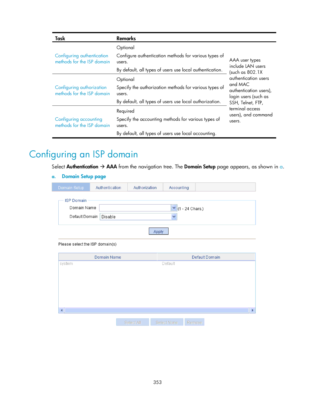
Domain Setup
Configuring an ISP domain
ISP domain configuration items
Configuring authentication methods for the ISP domain
355
Configuring authorization methods for the ISP domain
Authorization method configuration
Authorization method configuration items
Configuring accounting methods for the ISP domain
Real-time accounting updates for the users
Network diagram for AAA configuration example
AAA configuration example
Method Used Not Set -Uses the default accounting methods
∙ None -Performs no accounting
359
Configure a local user
360
Configure ISP domain test
Configure the ISP domain to use local authentication
361
Configure the ISP domain to use local authorization
362
Configure the ISP domain to use local accounting
Security and authentication mechanisms
Radius configuration
Introduction to Radius
Client/server model
Basic message exchange process of Radius
Basic message exchange process of Radius
Radius packet format
Radius packet format
Main values of the Code field
Code Packet type Description
Attribute
Radius attributes
Extended Radius attributes
Radius configuration task list
Configuring Radius
Segment of a Radius packet containing an extended attribute
TaskDescription
Radius server configuration
Configuring Radius servers
Configuring Radius
Parameters
Return to Radius configuration task list
Configuring Radius parameters
NAS-IP
Radius parameter configuration Radius parameters
Set the maximum number of transmission attempts
Timeout Retransmission Times
Attempts cannot exceed
Is an integer
Network diagram for Radius server configuration
Radius configuration example
Number of users Real-time accounting interval in minutes
Can be
Configure the Radius authentication server
Configure Radius parameters
Create an ISP domain
Configuration progress dialog box
Configuration guidelines
Configuring a local user
Configuring users
Users
Local user
User cannot pass authentication and therefore cannot log
Local user configuration Local user configuration items
Username Specify a name for the local user Password
User group list User group configuration
Configuring a user group
Vlan ACL
381
Specify the user profile for the user group
User group configuration items
User group after the users pass authentication
PKI overview
PKI configuration
PKI terms
Architecture of PKI
Entity
Applications of PKI
PKI repository
PKI architecture
Operation of PKI
Configuring PKI
Secure email
Web security
Creating a PKI
Creating a PKI entity
Domain
Generating an RSA
Requesting a Certificate Automatically
388
PKI entity list PKI entity configuration
Creating a PKI entity
Creating a PKI domain
PKI entity configuration items
PKI domain list
Fqdn
Select the local PKI entity
PKI domain configuration PKI domain configuration items
CRL URL
Ldap IP
Key Length Type the length of the RSA keys
Generating an RSA key pair
Destroying the RSA key pair
Retrieving a certificate
394
Get File From PC Specify the path of the file on the device
395
Requesting a local certificate
CRL
Retrieving and displaying a CRL
Configuring a PKI entity to request a certificate from a CA
PKI configuration example
398
PKI entity list Configure a PKI entity
399
PKI domain list Configure a PKI domain
400
Certificate list Generate an RSA key pair
401
Certificate list Retrieve the CA certificate
Certificate list
402
Request a local certificate
Configuring a port isolation group
Port isolation group configuration
Configure a port isolation group
403
Port isolation group configuration items
Port isolation group configuration example
Networking diagram for port isolation group configuration
404
405
Configure isolated ports for an isolation group
Configuring authorized IP
Authorized IP configuration
IPv4 ACL Associate the Telnet service with an IPv4 ACL
Web IPv4 ACL Associate the Http service with an IPv4 ACL
Authorized IP configuration example
Authorized IP configuration example
Network diagram for authorized IP
Create an ACL
408
Configure an ACL rule to permit Host B
409
Configure authorized IP
ACL overview
ACL configuration
Introduction to IPv4 ACL
IPv4 ACL classification
Effective period of an ACL
IPv4 ACL category Depth-first match procedure
Fragments filtering with IPv4 ACLs
Depth-first match for IPv4 ACLs
Benefits of using the step
Configuring an ACL
Configuring an IPv4 ACL
ACL step
Describes the configuration items for creating a time range
Configuring a time range
Time range configuration items
For creating a time range
Return to IPv4 ACL configuration task list
Configuring a rule for a basic IPv4 ACL
IPv4 ACL configuration items
Creating an IPv4 ACL
415
For configuring an basic IPv4 ACL
Configuration items for a basic IPv4 ACL rule
416
Configuring a rule for an advanced IPv4 ACL
417
For configuring an advanced IPv4 ACL
Configuration items for an advanced IPv4 ACL rule
TOS
Configuring a rule for an Ethernet frame header ACL
Dscp
Source Mask
For configuring a rule for an Ethernet frame header ACL
421
Encapsulation by configuring the following items
∙ Lsap Type-Indicates the frame encapsulation format
Networks without QoS guarantee
QoS configuration
Introduction to QoS
QoS requirements of new applications
Countermeasures
Impacts
Traffic congestion causes
423
End-to-end QoS model
End-to-end QoS
Traffic classification
DS field and ToS bytes
Packet precedences
Description on IP Precedence
IP Precedence decimal IP Precedence binary Description
Dscp value decimal Dscp value binary Description
Description on Dscp values
An Ethernet frame with an 802.1Q tag header
426
SP queuing
Queue scheduling
802.1Q tag header
Description on 802.1p precedence
Schematic diagram for WRR queuing
Schematic diagram for SP queuing
WRR queuing
428
Traffic evaluation and token bucket
Line rate
Evaluate traffic with the token bucket
429
Priority mapping
What is priority mapping
How line rate works
Line rate implementation
Introduction to priority mapping tables
Default CoS to DSCP/CoS to Queue mapping table
Priority mapping process
Input CoS value Local precedence Queue
Configuration task lists
QoS configuration
Configuring a QoS policy
Default Dscp to CoS/DSCP to Queue mapping table
Configuring line rate
Configuring queue scheduling
Configuring the priority mapping tables
Perform the task in 1 to configure queue scheduling
Creating a class
Configuring priority trust mode
Return to QoS policy configuration task list
Configuring match criteria
For configuring match criteria
Shows the configuration items of configuring match criteria
Define a match criterion to match Dscp values
Service Vlan
Does not overwrite the previous one
Values are automatically arranged in ascending order
Configuration items of creating a behavior
Describes the configuration items of creating a behavior
Creating a traffic behavior
For creating a traffic behavior
438
Port setup page for a traffic behavior
Traffic directing on the chassis front panel
439
Configuring other actions for a traffic behavior
For setting a traffic behavior
Describes the configuration items of creating a policy
Configuring classifier-behavior associations for the policy
Configuration items of creating a policy
Creating a policy
Applying a policy to a port
For setting a policy
Behavior Name
441
Configuration items of applying a policy to a port
Configuring queue scheduling on a port
For configuring queue scheduling
For applying a policy to a port
WRR
Configuring line rate on a port
Return to Queue scheduling configuration task list
For configuring line rate on a port
Configuring priority mapping tables
Configuration items of configuring line rate on a port
Return to Line rate configuration task list
Configuration items of configuring priority mapping tables
Configuring priority trust mode on a port
For configuring priority mapping tables
Port priority configuration items
For configuring port priority For modifying port priority
Describes the port priority configuration items
447
Return toPriority trust mode configuration task list
ACL/QoS configuration example
ACL/QoS configuration examples
Network diagram for ACL/QoS configuration
448
449
Define a time range covering 800 to 1800 every day
450
Create an advanced IPv4 ACL
451
Define an ACL rule for traffic to the FTP server
452
Create a class
453
Define match criteria
454
455
Configure actions for the behavior
456
Configure classifier-behavior associations for the policy
Create a policy
457
PoE power
PoE configuration
PoE overview
Advantages
Protocol specification
Configuring PoE
Configuring PoE ports
Protocol specification related to PoE is Ieee 802.3af
Port setup PoE port configuration items
461
Configuring non-standard PD detection
PSE setup
Displaying information about PSE and PoE ports
PoE configuration example
PoE summary with GigabitEthernet 1/0/1 selected
462
463
Network diagram for PoE
464
Configure the PoE port supplying power to AP
Support and other resources
Command conventions
Contacting HP
Related information Conventions
Symbols
Subscription service
GUI conventions
Network topology icons
467
Index
Page
Page