Introduction
1.5Outside Enclosure Overview
The enclosure for the Universal Monitor’s controller board comes in two sizes:
•The large enclosure is designed to accommodate the Transformer Module and future compo- nents, in addition to the controller board.
•The small enclosure is built to hold the controller board only.
Both enclosures are
Both enclosures have a
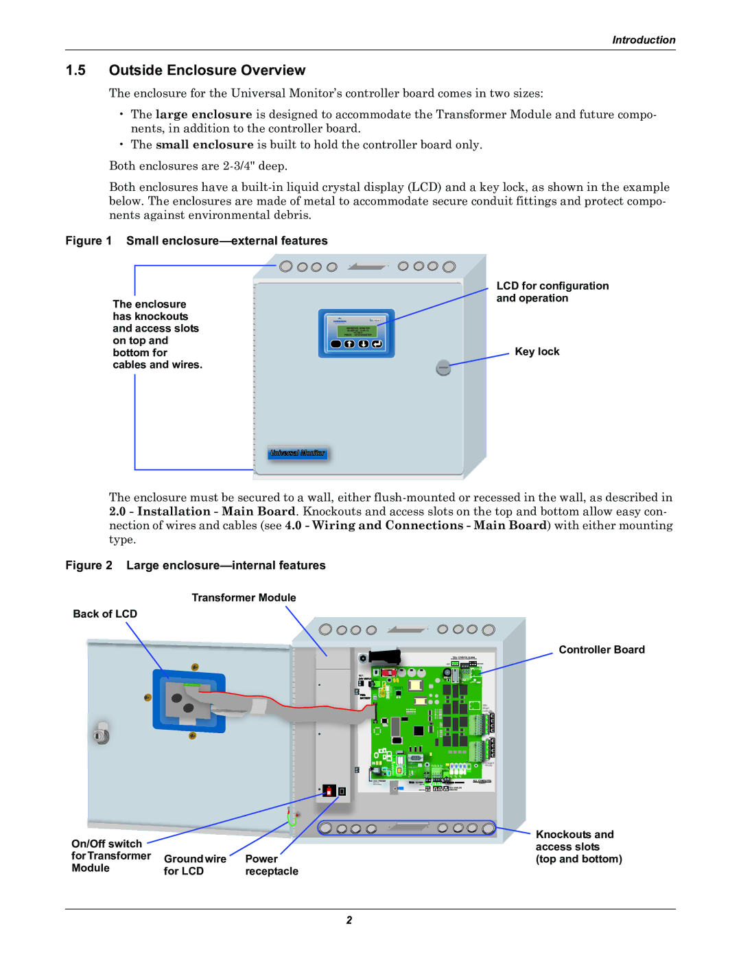
Figure 1 Small enclosure—external features
The enclosure has knockouts
and access slots |
|
|
|
|
| PRESS =STATUS/SETUP |
| ||
|
| UNIVERSAL MONITOR |
| |
|
|
| ||
on top and |
| V5.100.0 |
| |
|
|
|
| |
ESC |
| |||
bottom for |
|
|
|
|
cables and wires. |
|
|
|
|
LCD for configuration and operation
Key lock
Universal Monitor
The enclosure must be secured to a wall, either
2.0- Installation - Main Board. Knockouts and access slots on the top and bottom allow easy con- nection of wires and cables (see 4.0 - Wiring and Connections - Main Board) with either mounting type.
Figure 2 Large enclosure—internal features
Transformer Module
Back of LCD
Controller Board
TB5: COMMON ALARM | |
(TERMINAL BLOCKS ROTATED IN VIEW) | |
NO C NC | NO C NC |
(TOP) | (BOTTOM) |
TB7: |
|
24V INPUT |
|
BAR CODE | LIEBERT |
TB3:
RELAY
OUTPUTS
(BOTTOM))
| (TOP) |
| 8 |
| 4 |
| 7 |
| 3 |
| 6 |
| 2 |
| 5 |
| 1 |
REV | (BOTTOM)) |
(TOP) | |
| 8 |
| 4 |
| 7 |
| 3 |
| 6 |
| 2 |
| 5 |
| 1 |
ASS | TB2: |
CONTACT | |
| INPUTS |
MODEM |
|
J11: PHONE | 0: COMMS |
|
| ALL CIRCUITS; |
PIN | + — |
| CLASS 2 | |
PIN | (TOP) | + — + — |
| |
ON |
| 485 |
| TB9: ANALOG |
|
|
| ||
| (BOTTOM) + — | + — + — | GROUND | |
On/Off switch |
|
|
|
|
| Knockouts and |
|
|
|
|
| ||
|
|
|
|
| access slots | |
for Transformer | Ground wire | Power |
| (top and bottom) | ||
Module | for LCD | receptacle |
|
| ||
2